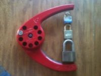
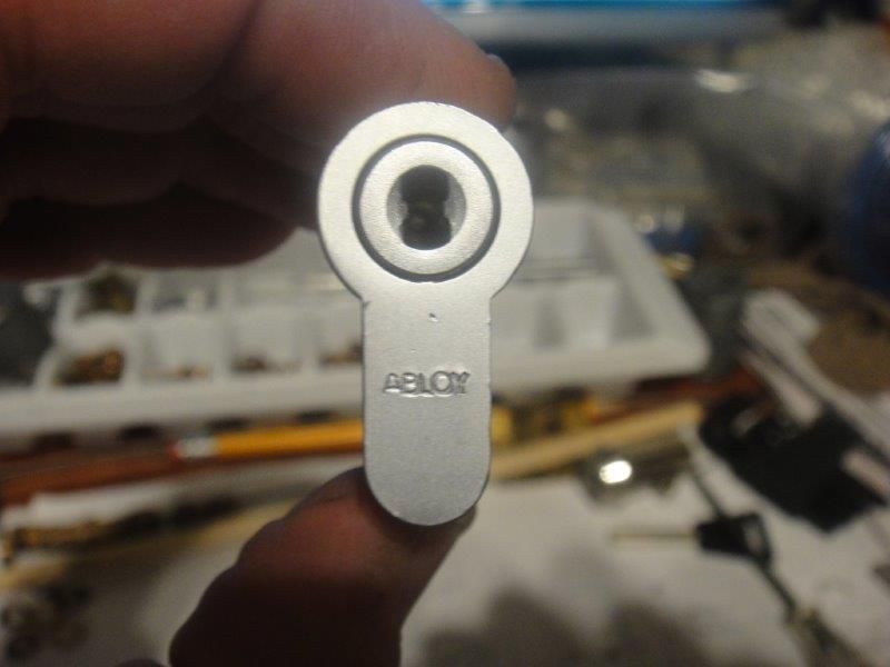
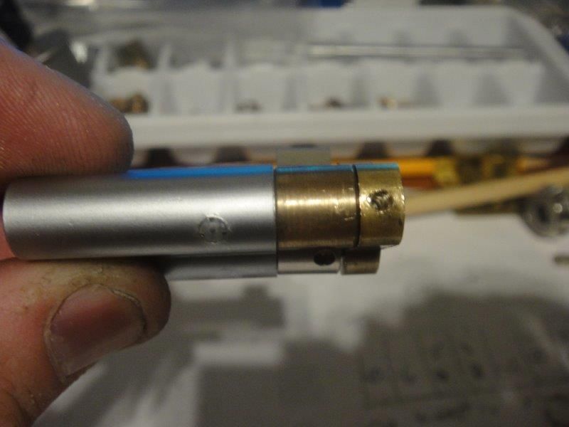
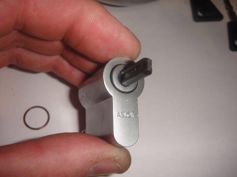
This is the breakdown of a half-euro profile ABLOY Disclock cylinder.
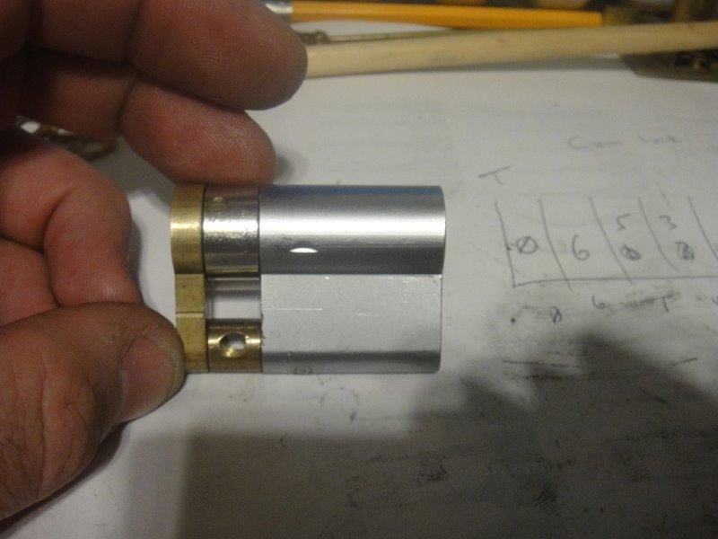
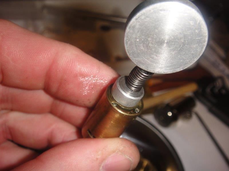
There was a pin in this hole. Due to splines on the pin, it was much easier to drill out the pin, which I replaced with the threaded part of a bicycle spoke upon reassembly.
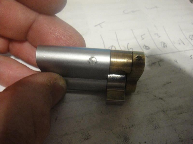
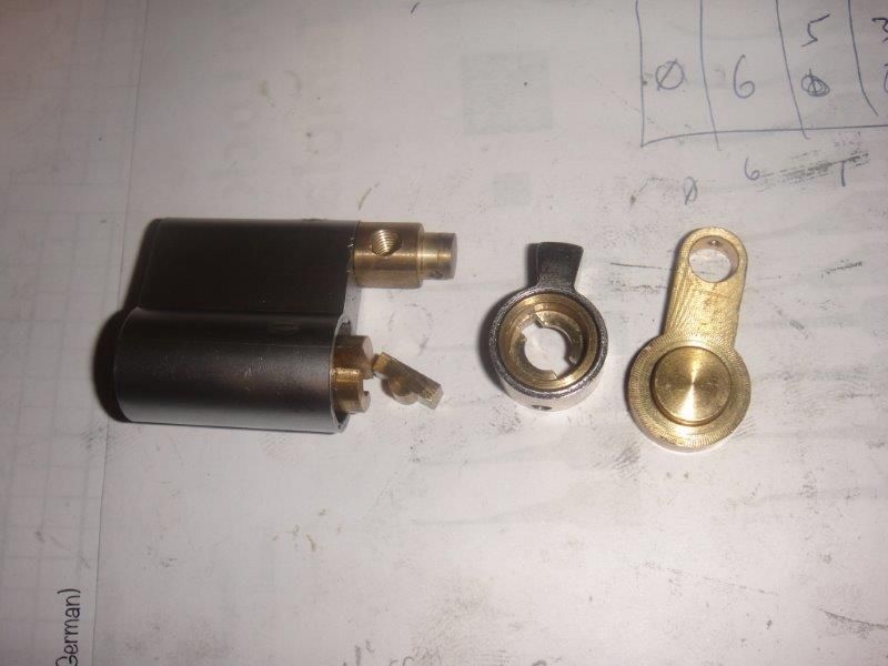
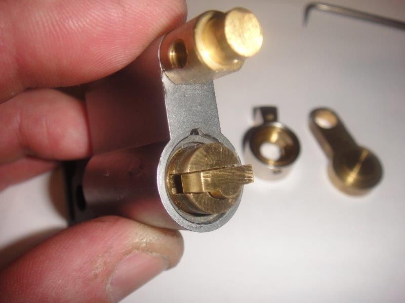
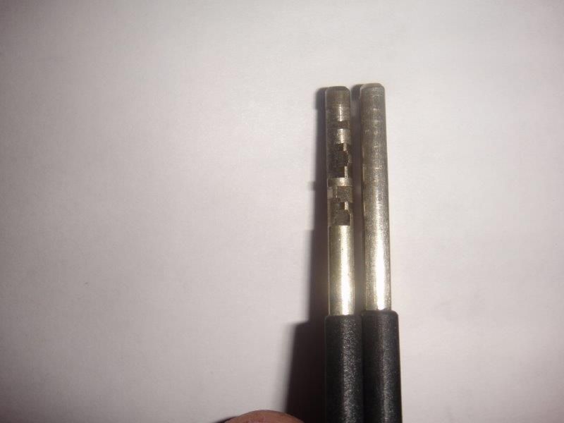
The end, actuator, and part that splines into the actuator when the key is inserted then slide off. Being a half euro profile cylinder, I see no reason for the moving part that splines into the actuator other than it is cheaper to only make one type of plug.
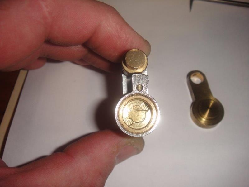
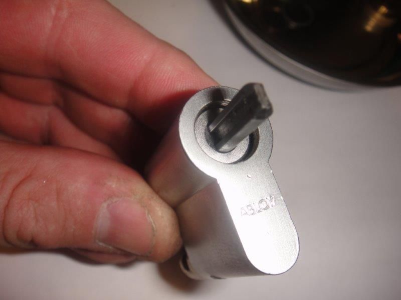
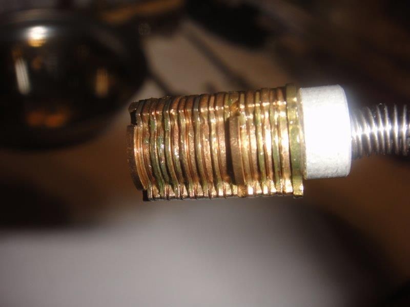
This is what it looks like when the actuator is not lined up. In a dual cylinder or thumb turn lock, this is how the one key is able to work the lock. One side or the other at a time can be splined with the actuator, pushing out the other side.
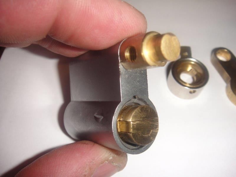
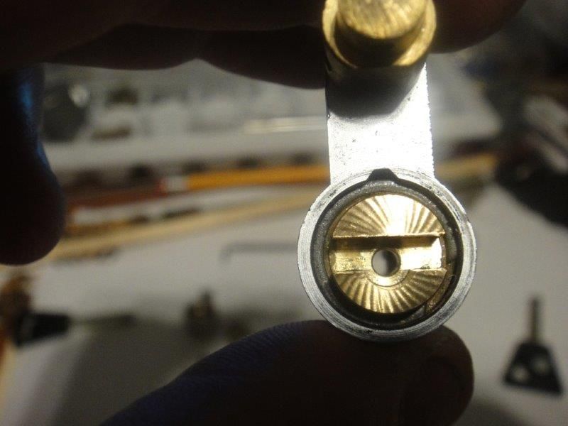
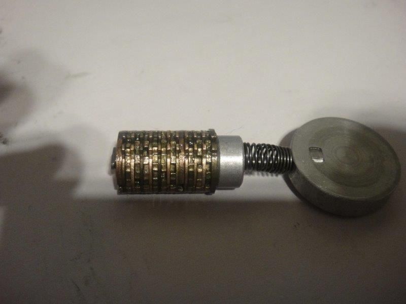
With the actuator removed, here is how the moving piece (Somebody please tell me the correct term!) looks when there is no key in the lock.
And with the key inserted fully
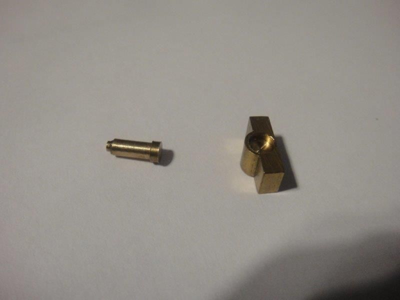
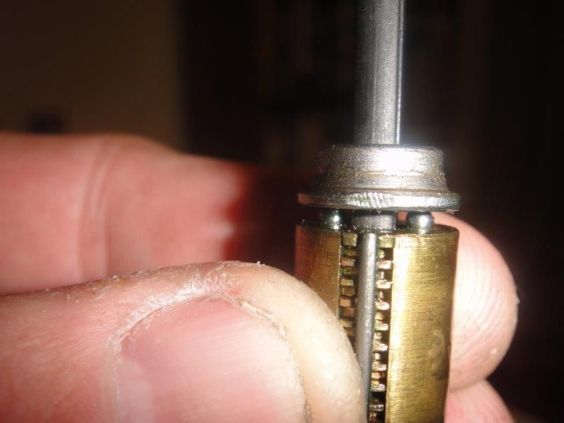
Here is the moving piece, and the push rod that the key acts on to move the spline.
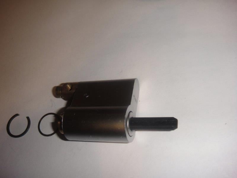
With the push rod and moving piece removed, you can see the clip that retains the plug in this lock.
The clip and spacer behind it are removed. There is an alignment tool (essentially a plastic blank key with no bow) that I put into the lock in case the plug started to slide out the back of the lock.
The lock from the front ready to have the plug removed
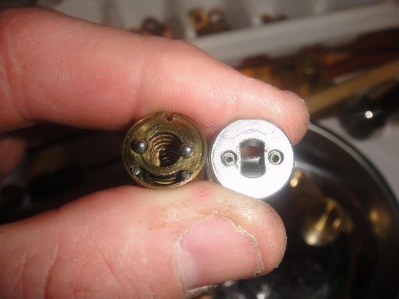
With the plug removed out the back, you can see the plug, spacers, discs, and sidebar. The two balls fit into index holes in the top spacer (even with the top of the sidebar), allowing you to know when you can turn the key back to the neutral position and remove the key.
The top piece that is the front of the plug inside the lock has 2 holes with springs which act on the two bearings for sure indexing. You can also see the two return bars at the bottom of the plug.
The tool is installed which will hold together the disc and spacer pack.
The bottom of the disc and spacer pack.
The top of the stack. Note that the discs are scrambled.
A blank and the key to which I will key this lock.
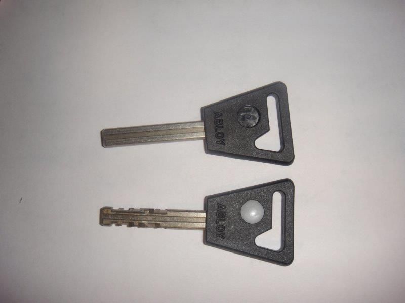
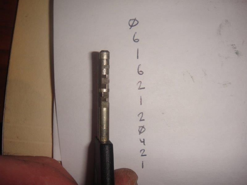
The key is read from tip to bow. For more information on reading the key, see my other post. I have written the cuts of the key in order from tip to bow.
These are the discs and spacers laid out in order for reassembly. The discs for the tip of the key are to the left, and progress to the right. If you look at the circled area, you can see that I almost messed up and installed a one-way spacer into the lock. This would only allow the key to either lock or unlock, but not both.
That about covers it for this lock! For reassembly instructions, read this post backwards.
Gordon