by zeke79 » 4 Feb 2009 4:51
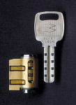
The miwa cam locks are fairly easy to open without prior knowledge of the key. The keys have 8 magnets but the sliders are one piece which contain two magnets, one for each side of the key so the locks only contain four sliders (in my limited testing as I only have a few of these locks). I believe I have done a breakdown of the process in the advanced forums. There is only 3 possible codings if memory serves me correctly and that is positive, negative, and neutral. If you take into account that you only have to work with one side of the key you only have 4 to the third power or 64 possible differs though I have found that working with powerful enough magnets that number is reduced.
This post actually brings up an old pick design I worked on that I worked on making. The prototype blank was milled of a block of pvc with a large keyhead holding two 3v coin cells in series and four milled disk areas with proper spacing of the slider locations on one side of the blank. The other side was used to run thin coated wired collected from small motor windings which lead to home made electro magnets which could be controlled from the key bow to switch polarity from positive to negative to neutral in each disk location. The problem I ran into was getting enough power from the very tiny electro magnets I had made to actuate the sliders. I am not sure if the problem lies in problems with current induction between the wires for each magnet or a lack of overall current from the coin cells. In the end, the project was abandoned as it is just too easy to manually duplicate the same process and in solving the issues of lack of battery current capability, the size of the key bow with larger cells and the switching setup was just going to be too cumbersome looking. These issues combined with no real "need" for the tool lead me to the decision to abandon the idea for now. As said however, the process can be duplicated very simply with rare earth magnets and a spring steel street sweeper bristle along with a simple code chart to document coding attempts and speed the process by organizing magnet polarity changes most efficiently.
I may one day mill out a new blank with a larger head assembly to allow the use of either a single 9V cell or AAA cells. If these cells are used, I will need to find a stronger material to prototype with as the weight of a pair of AAA cells or a single 9V would likely stress the milled out key blank to key head junction to the point of breaking. I have not tested a 9V, but it may carry too much voltage and current for the small gauge wire to handle so the best suited match would likely be the AAA cells as if nimh cells were used a lower overall voltage and higher current capability will offer a number of different wiring options depending on the number of cells used. A higher voltage and lower current capability could be yielded or a lower voltage and higher current configuration could be yielded. With 4 AAA cells one could obtain a 1.2V configuration with high current capability or a middle of the road approach would be 2.4v with a mid level current capability or a low current 4.8V configuration could be used with 4 cells. It would just take some testing to see which configuration yielded the strongest electro magnets while not overheating the micro switches or wire used for polarity changes.
It could be a fun project if someone wants to take the time to do it or if someone has the need for such a device. The only type of application I could think of that would actually be worth the time to make the tool would be for someone who dealt with the locks on a regular basis in a setting such as a spam, vending, etc environment.
For the best book out there on high security locks and their operation, take a look at amazon.com for High-Security Mechanical Locks An Encyclopedic Reference. Written by our very own site member Greyman! A true 5 Star read!!