Have already done posts on how to get out the locking cam assembly using stuff you can find anywhere. This post is on making a 'proper' disassembly tool, similar to the one sold by Best.
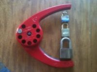
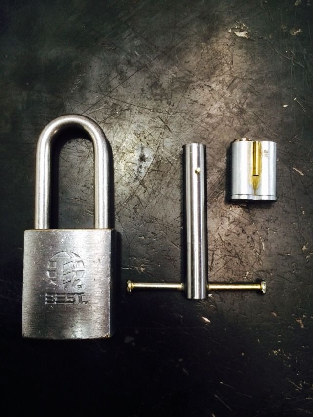
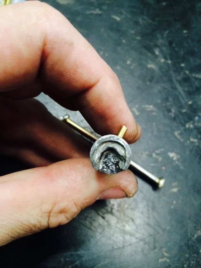
Here is the completed tool, between a padlock and core.
The tool works by compressing the spring on the locking cam assembly and rotating partly under the cam, then rotating the plate on the cam so it lines up with the groove in the lock body. Then the locking cam assembly can be removed. It takes about a second or two.
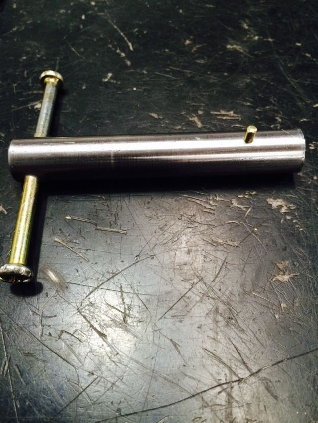
Made from 1/2" diameter steel rod, two screws with a long, threadless neck below the head of the screw, and a 3/32" brass rod for the alignment peg, this costs considerably less to make than the roughly $100 Best Access Systems charges for the tool.
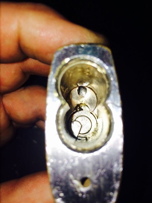
Here is the padlock with the core removed.
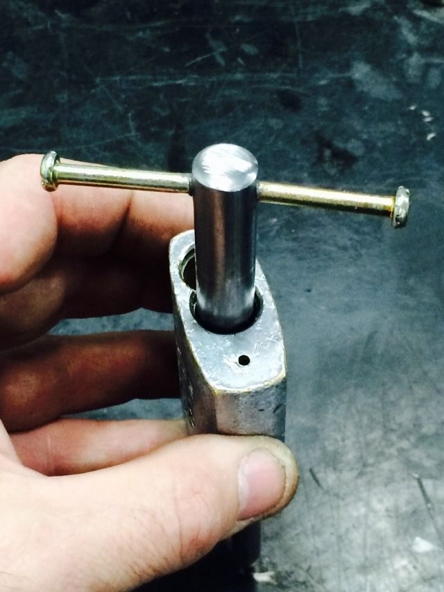
Put the tool in the lock with the alignment peg turned to the right.
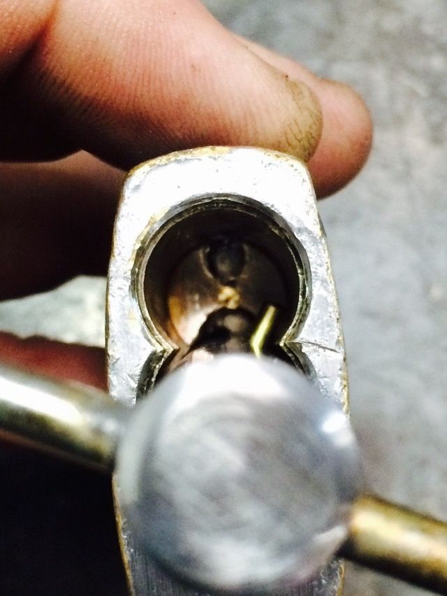
Push the tool inwards to compress the spring, then turn it to the right until it stops lightly. The alignment peg will be centered when it is properly turned.
Then pull out the locking cam.
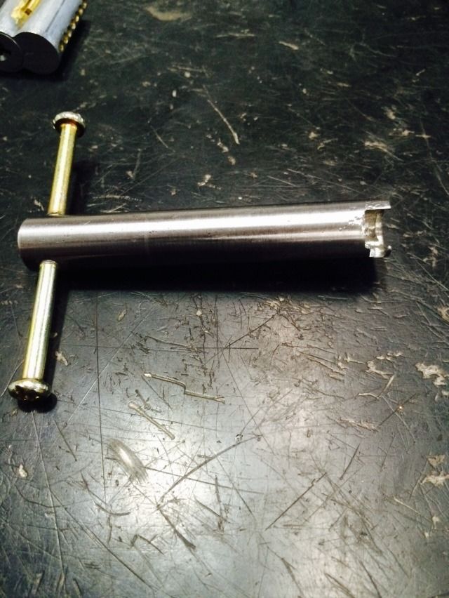
OK, time for info on making the tool. It is easier to show how it is cut by drawing it on a wood dowel.

All measurements are here:
The easiest way to get the size and shape right is to scale the first picture of the dowel so it prints at 1/2" diameter. (About 12.6 mm). Tape or glue it to the steel rod, and use a dremel to cut it out.
The dotted line is cut shallower than the solid line.
Good luck!
Gordon