Of course they talk it up.
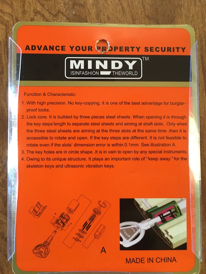
A preview teaser for oldfast...


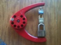
The keys should remind you of the Pagoda locks. These locks do operate the same way.


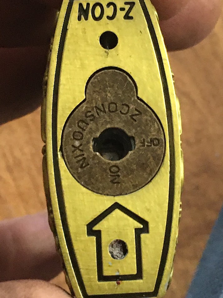
Note this next picture. Not for the keyway shape, but that it is labelled like a switch lock - OFF and ON. Funny enough, OFF is locked and ON is unlocked.
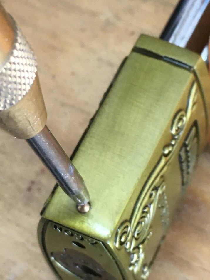
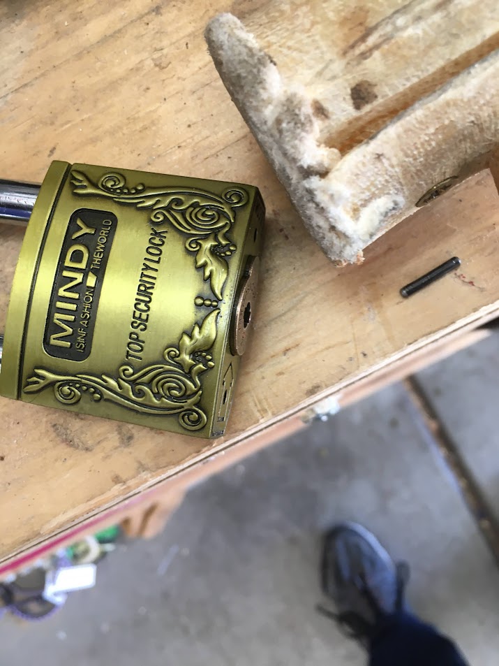
On the side of the lock, down low there is a poorly fitted brass pin. You will need to remove this pin for disassembly. The lock is low enough quality that I'm not too worried about it qualifying as DE.

Use a center punch since the pin is round surfaced, then drill it out. It is only a few millimeters long - just over the width of the walls of the lock body.


Now tap the side of the lock body above the hole with a rawhide or rubber mallet. A long steel pin comes out of the hole. That is what keeps the core in the lock...


... along with some adhesion from the clear coat finish. Rap the corner of the padlock a couple times with that mallet.

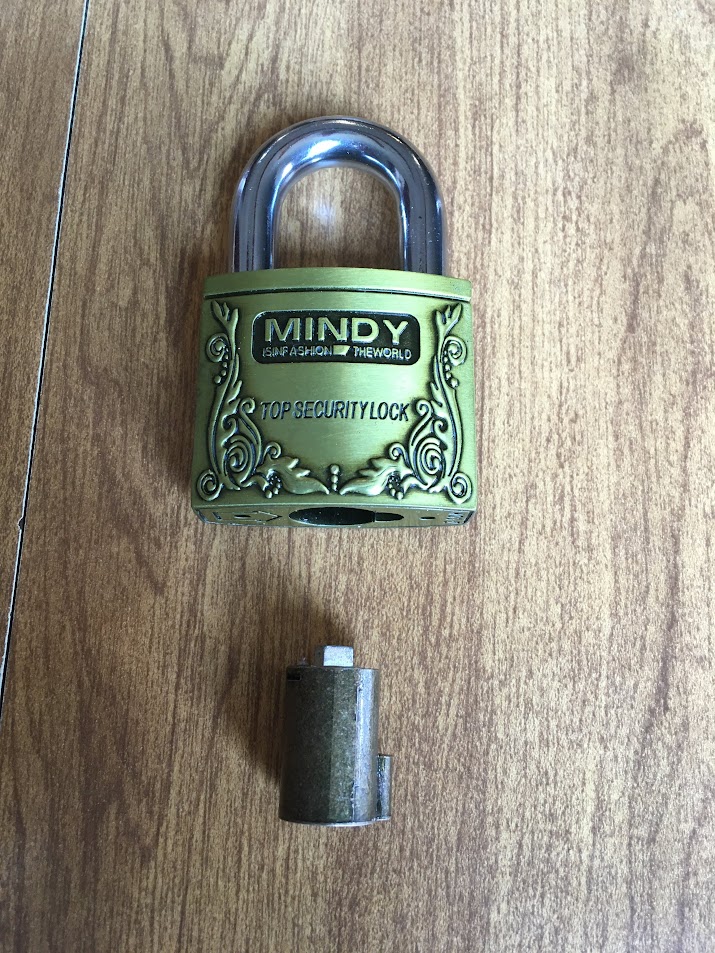
And here she comes! You may need to use the key or a hook to help pull out the core.
Core removed!
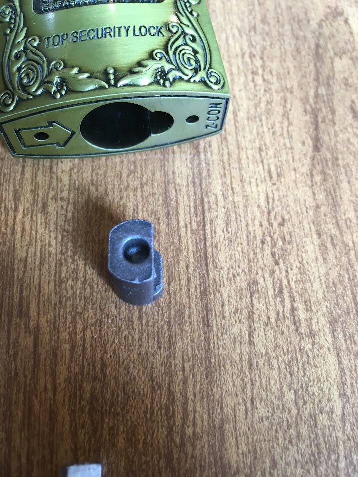
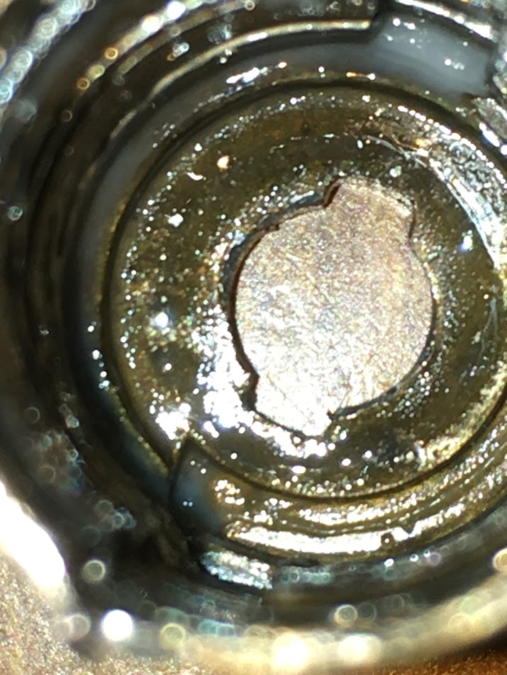
Now look in the padlock body, you see the actuator. This padlock uses locking balls, so it can't be shimmed.

The actuator is not completely cut on center (intentionally), even on the core end. Be sure to note which way it is oriented when you are disassembling. Use the cut sides of the outer edge to determine orientation. One side will be a little narrower than the other side. Also pay attention to which side is facing the core tab cutout. It will be important.

You may need to tap the padlock body on a table or wood block to get the actuator to come out. But now you can easily see the difference in sides cutouts I mentioned above.

The upper end of the actuator is very heavily cut back on one side. No mistaking which side that is. On reassembly, be sure to put that side to the core tab cutout.

Now lift out the shackle.

Now looking back into the padlock body, you start to see the locking balls. They are different sizes, so keep track of which one goes on the core tab cutout side. (The smaller one).

Here they are side by side. No, they don't come with that grease on them. Took this pic when getting ready for reassembly, and I could see that the lock would benefit from some lube.

Reminder - the cutout goes on the core tab side with the smaller ball. I am repeating this because it really matters.

The only parts left have to do with the core. So let's examine it.


The tab has a hole in it. That is where the long steel pin fits in to retain the core.


Each side, at the top of the core, has a window cut through it. Suspect this was for service, though it may be that they never intended the lock to be serviced.

The top of the core.

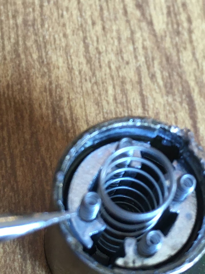
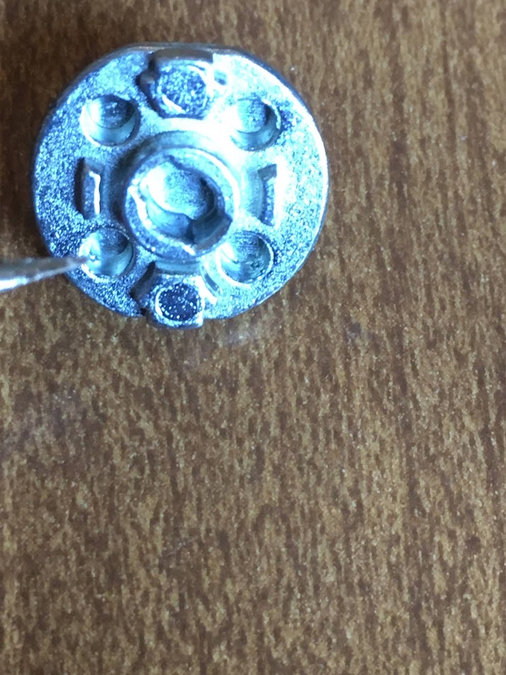
The driver that turns the actuator is held in place by a snap ring.

Remove the snap ring with a dental type hook pick and a fair amount of curse words, taking time to wipe off the blood as the hook pops loose repeatedly and hooks your thumb.


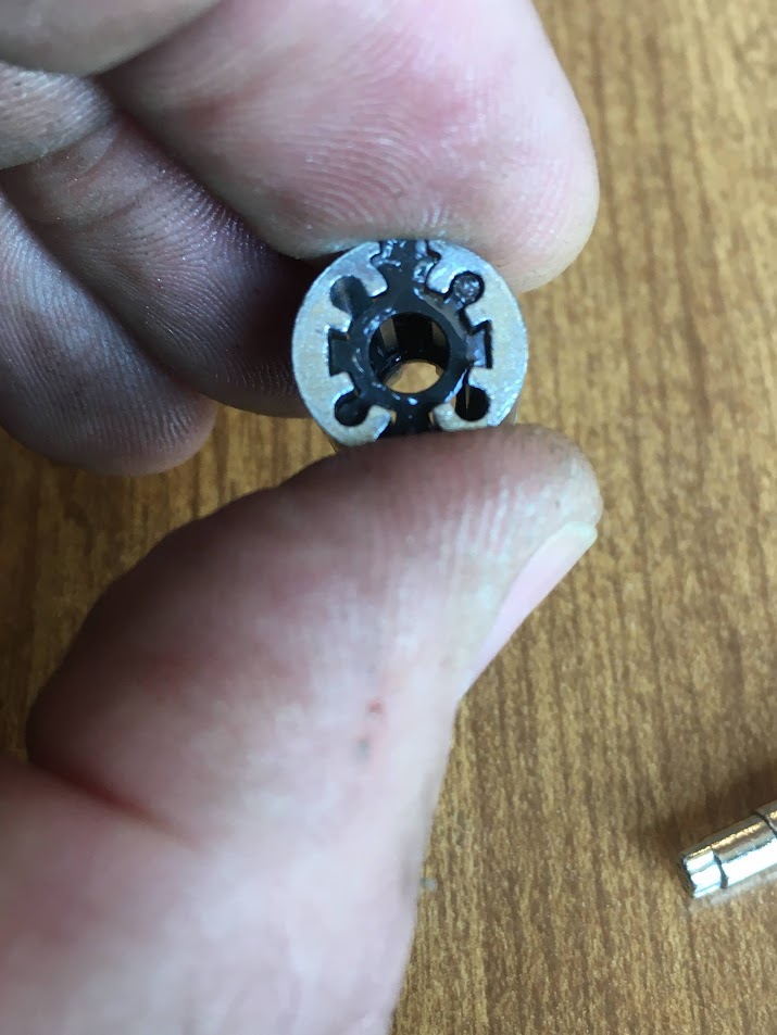
The driver will now be pushed up by the five springs inside the core. Remove it.


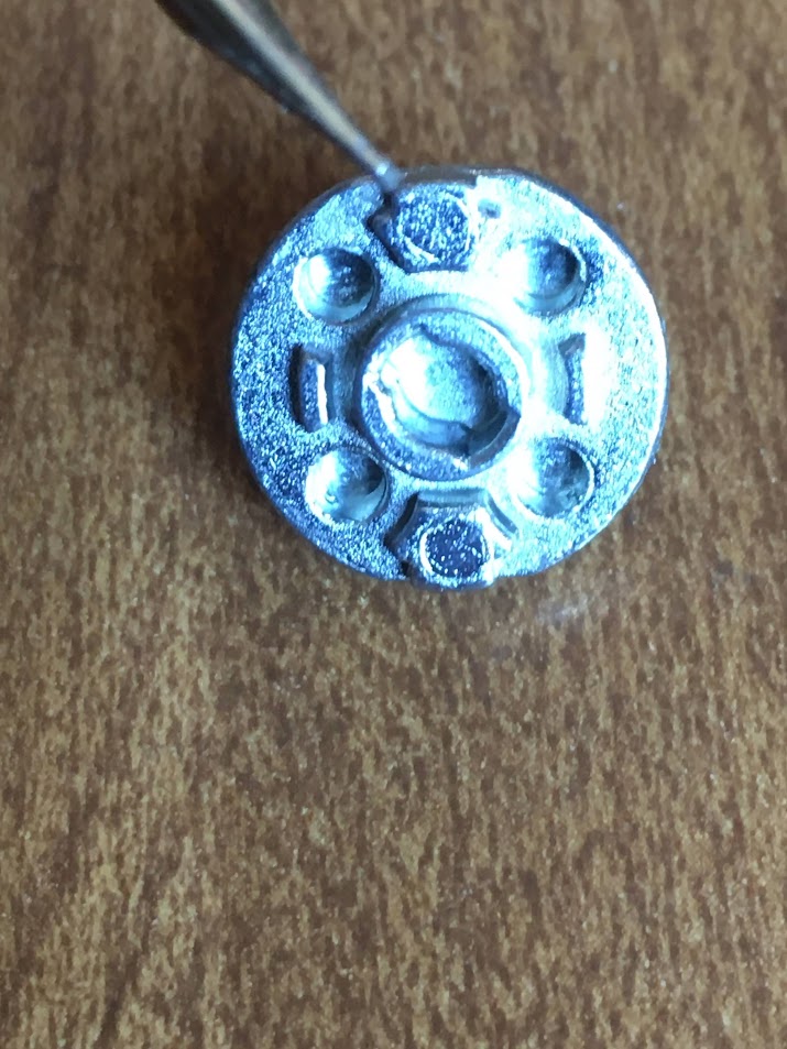
The inner side of the driver has a number of notable sections:

There are four smaller springs. Two diagonal springs operate the outermost locking disc and the two others operate the middle locking disc.
They fit into these holes.
This large spring operates the innermost locking disc.

It fits around the inner post in the middle of the driver.

These holes on the sides of the inside carrier actually turn the driver.

By engaging these stumps.
Remove the large spring

It fits on the driver like so:
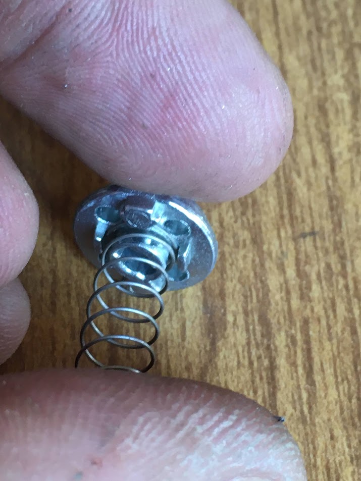
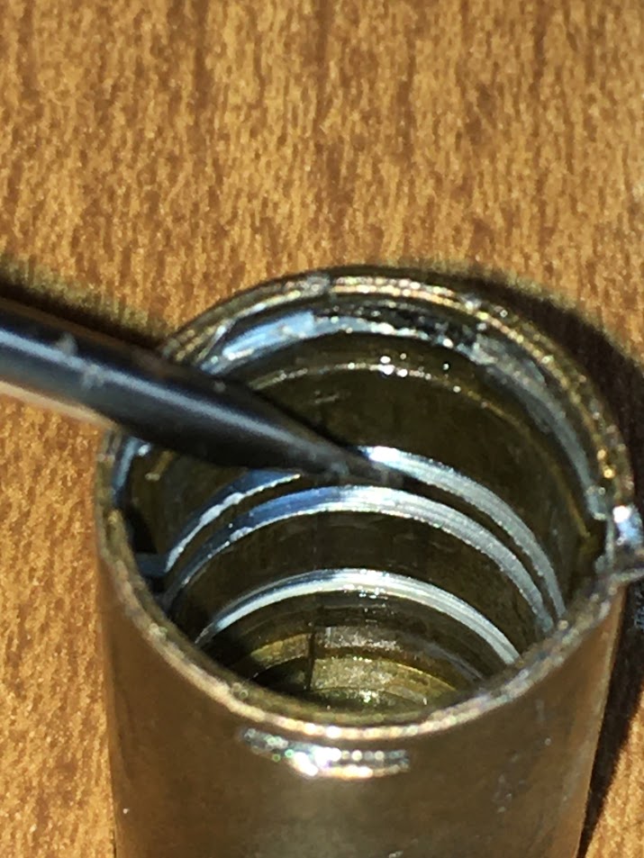
Now you can easily see the top end of the keyway, the four smaller springs and the innermost locking disc.

A better shot.

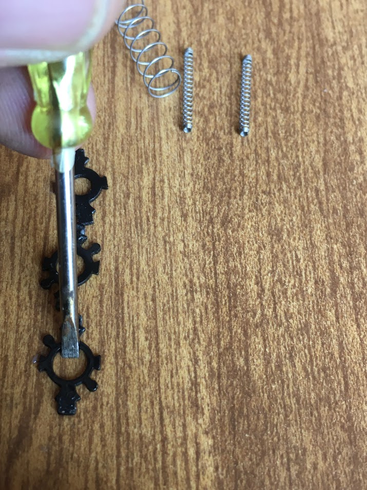
Remove the four narrow springs.


Now the carrier with the combination discs can be seen.
Keep your finger over the end of the carrier and tip the core over, tapping it until the carrier starts to come out of the core. Your finger is to keep the combination discs from falling out.

With the carrier removed, you can see the three combination disc ends sticking out from either side of the carrier. More on that in a moment.

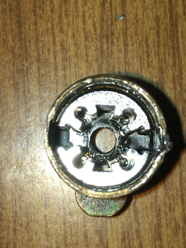
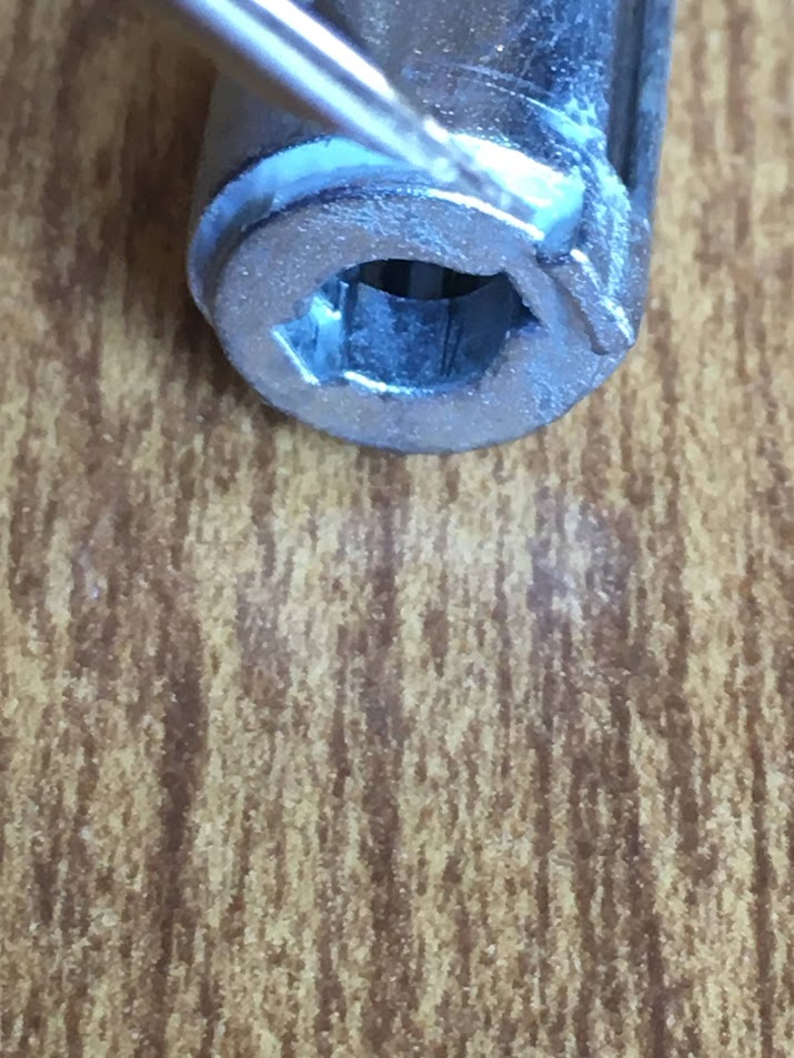
Looking in the core where the carrier was, you can see a couple grooves going all the way down, and three more going clear around the core.

The longitudinal grooves are where the combination discs slide when the key pushes them against the springs. The three grooves here:


Are where the key pushes each combination disc to allign with when the correct key is used. (Or picks

Pull out each disc, keeping track of the orientation.

The first one removed is the innermost from the keyway. It has the smallest center hole for the narrow tip of the pagoda key. It is the one driven by the large spring.

Lifted the second, middle combination disc to the top of the carrier so you can note the top right and bottom left corners have tabs, but the other two corners do not. These two tabs are what are driven by two diagonally opposite small springs.
Also note the angled tabs on the sides. These are to keep the disc from flipping sideways in the keyway.

The third disc, which has the largest diameter center hole, has tabs on the other two corners. That is important when reassembling, or the discs can't be pushed properly to their unlocking location.

A small screwdriver is used to show the difference in sizes of the center holes.


And the empty carrier. Note the number 7. I am fairly certain that indicates which key bitting is needed to operate that carrier.

Where the springs press:


This tab on the bottom of the carrier is used to limit turning of the key.
At the bottom of the picture of the core, you can see where the carrier tab operates and stops.
And finally, the exploded view of all the lock components (except for the brass pin we drilled out. For that, slightly flatten out a #6 length American padlock pin/#7 length Master padlock pin, or any other brass rod stock.

As always, feel free to comment, ask questions or make corrections.
Gordon