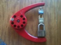
Received a few more locks that Snowyboy made! His work is downright amazing.
First, the family shot:
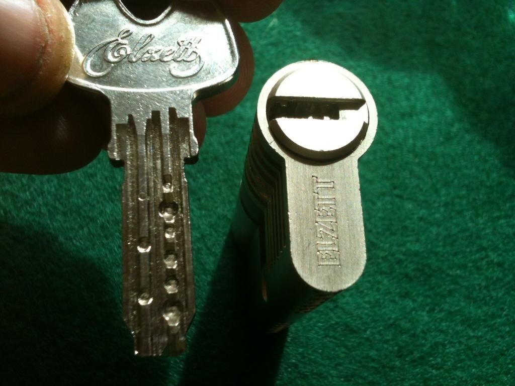
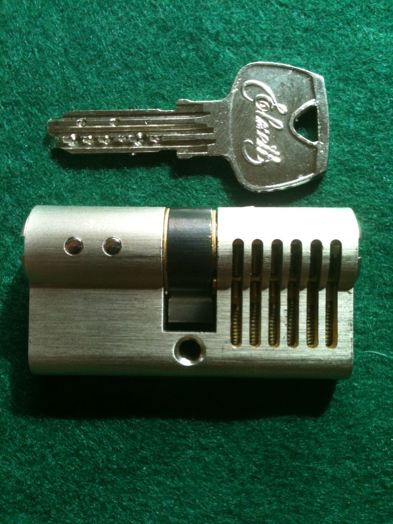
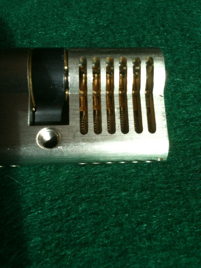
Top one is an elzett X-1 from our Hungarion friend. Then, sent out to the United Kingdom
so Snowyboy could work his magic.
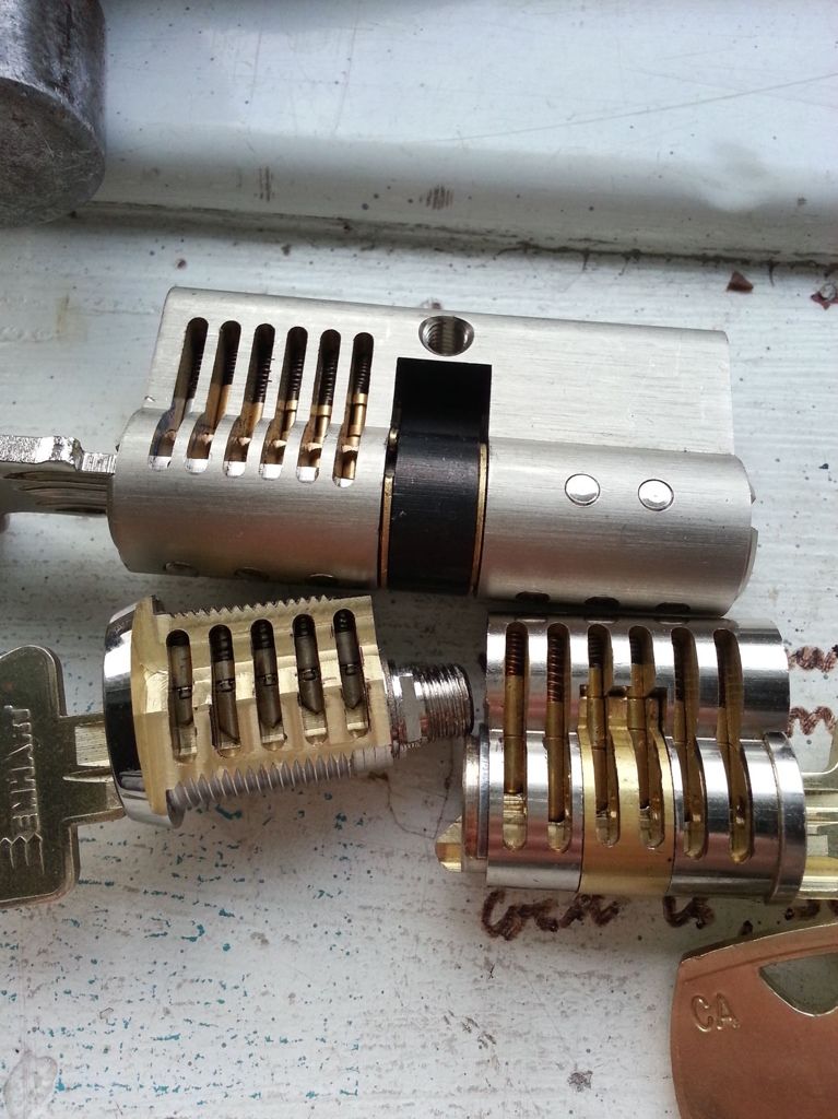
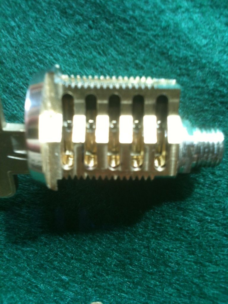
The X-11 key and lock face:
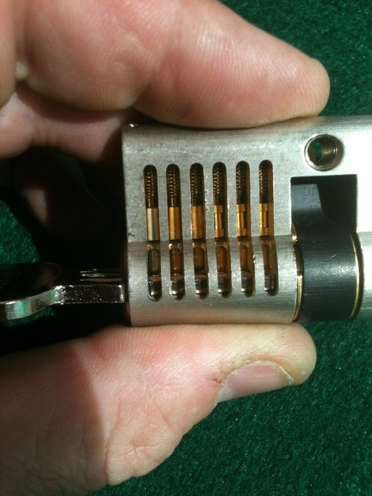
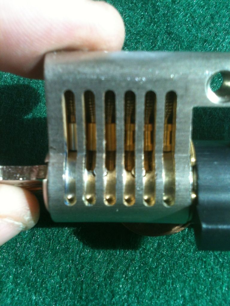
Profile view of the six primary pin channels cutaway…
Unfortunately my phone’s camera is not the greatest. Maybe will try with another camera soon. but here you see the pins in resting position. Part of the plug is milled away so you can see the key pins, but a lip is kept in place to keep the pins in correct alignment.
With the key inserted, you can see the pins lined up at the sheer line. The first pins are hardened steel for drill resistance. (You had better not get caught drilling my cutaways!!!)
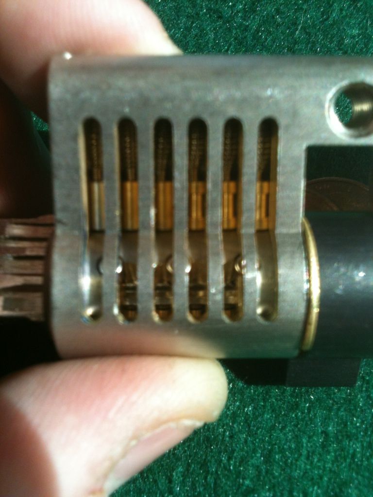
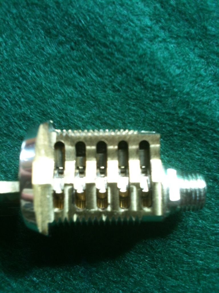
Key slightly turned to show the key pins. Yes, the lock is upside down in some of these pictures, but that was the only way to get the light correct for the shot.
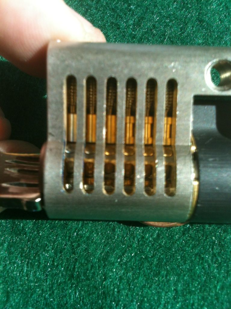
But there are still five more pins - two profile pins and three top pins opposite the six primary pins. Being Snowyboy, of course he has cut away the other side of the lock so those can be seen, too.
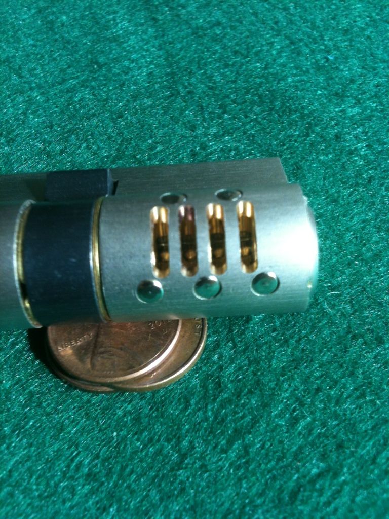
Back to the ‘front’ of the lock, here the key is turned to show the two profile pins:
And the three passive pins opposite the six primary pins…
And to the back of the lock to show the primary key pins seen through the other cuts:
The two profile pins:
And the three passive pins…
And before we move on to the next cutaway, a note on the five passive pins. They are spring loaded!
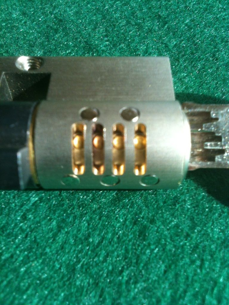
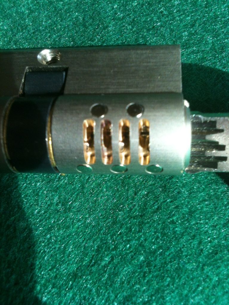
Next up, an Emhart cam lock.
Without the keys, you can see the pins not rotated correctly or lined up. Notice that at rest the driver pin and key pin are locked together, so this lock can not be bumped.
The next shots are very hard to take with my phone. Will see about using another camera later.
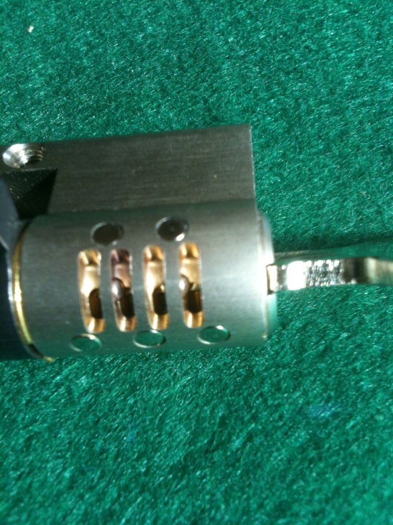
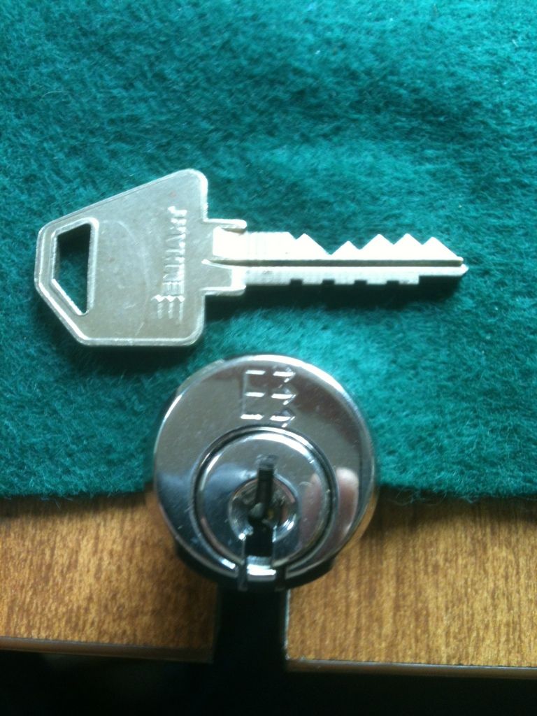
Here, the key is fully inserted, and the pins are aligned at the shear line and rotated correctly to line up with the groove cut into the plug.
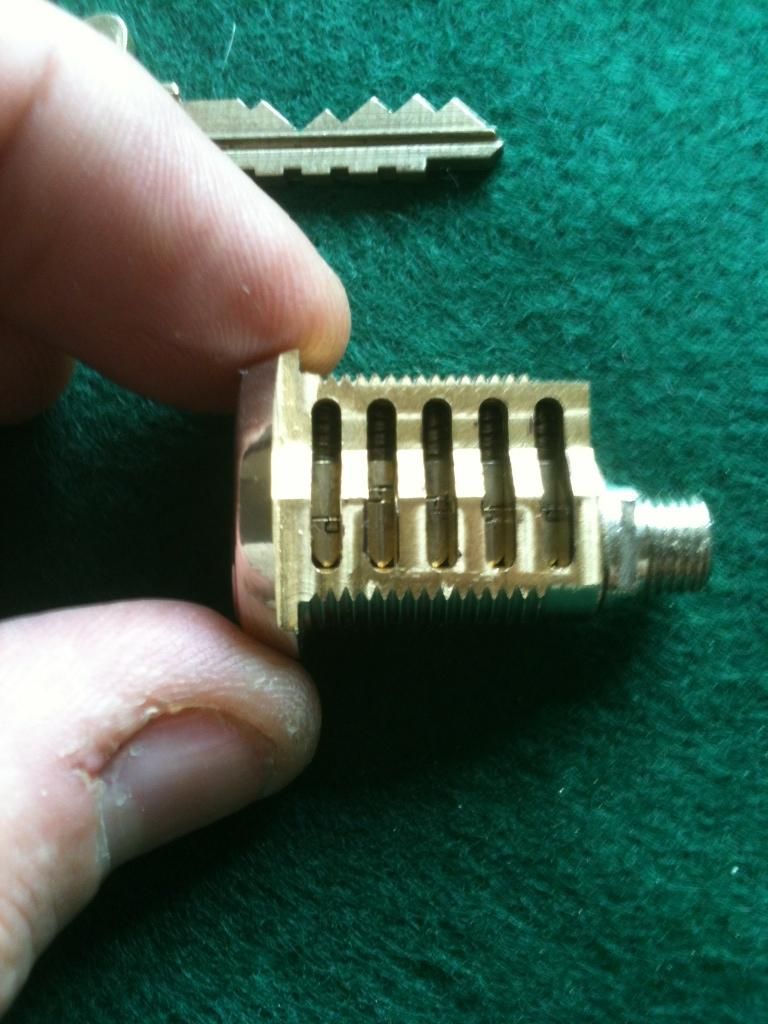
Here the key is turned slightly so you can see the tops of the key pins and the part that interlocks with the driver pins:
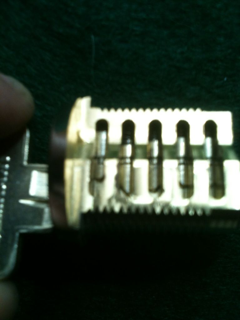
And the angle changed so you can see the bottoms of the driver pins and the groove/channel the goes around the plug, allowing for rotation/ The tops of the key pins are too bright in this picture to make out very well, hence the previous picture.
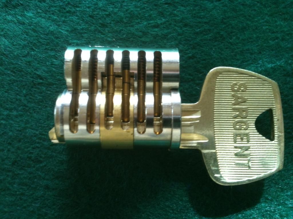
And last (just to make Jeff wait
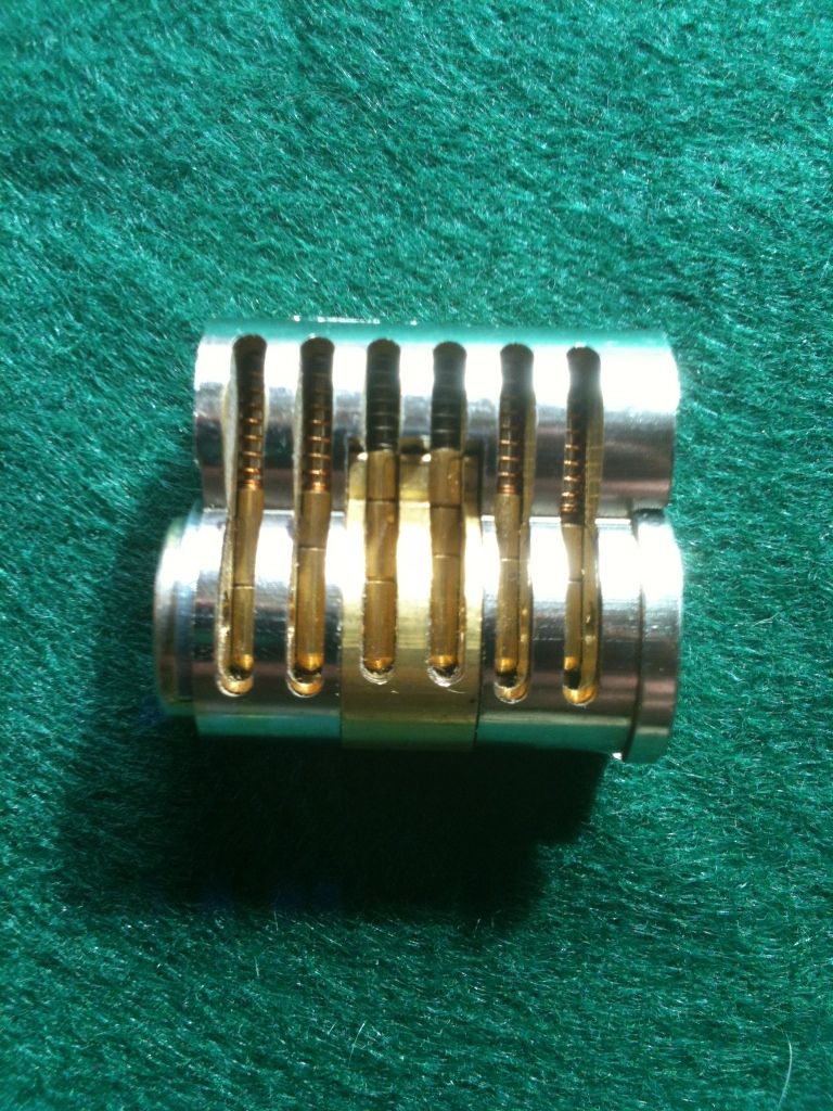
Side view showing all the pins:
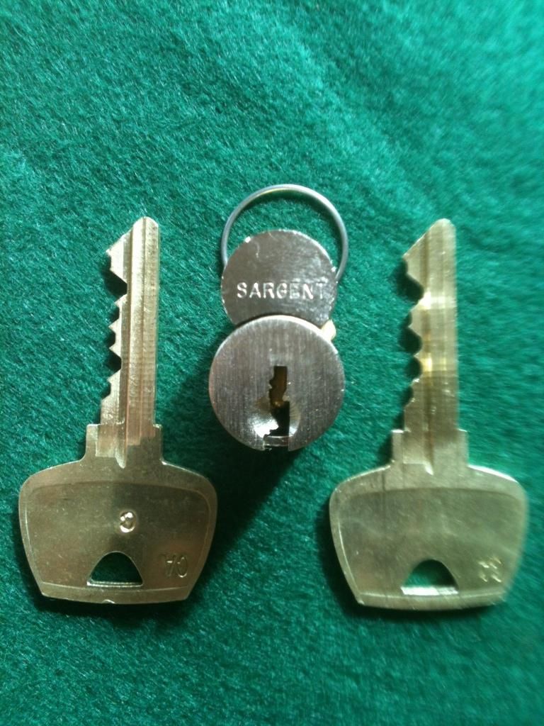
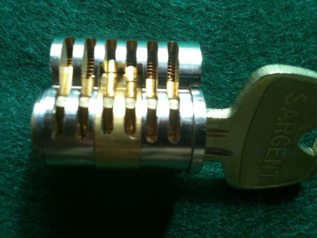
The change (operating) key inserted, the operating pins all line up at the sheer line.
And turned with the change key..
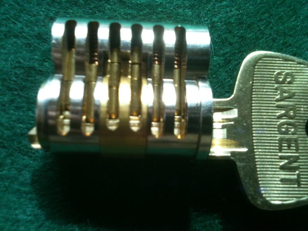
Now the control key inserted. Note that the two middle pins are the only pins used for control with a Sargent LFIC, while the first two and last two pins are unchanged. There are a number of LFIC cores that work this way. Best SFIC cores do not work this way.
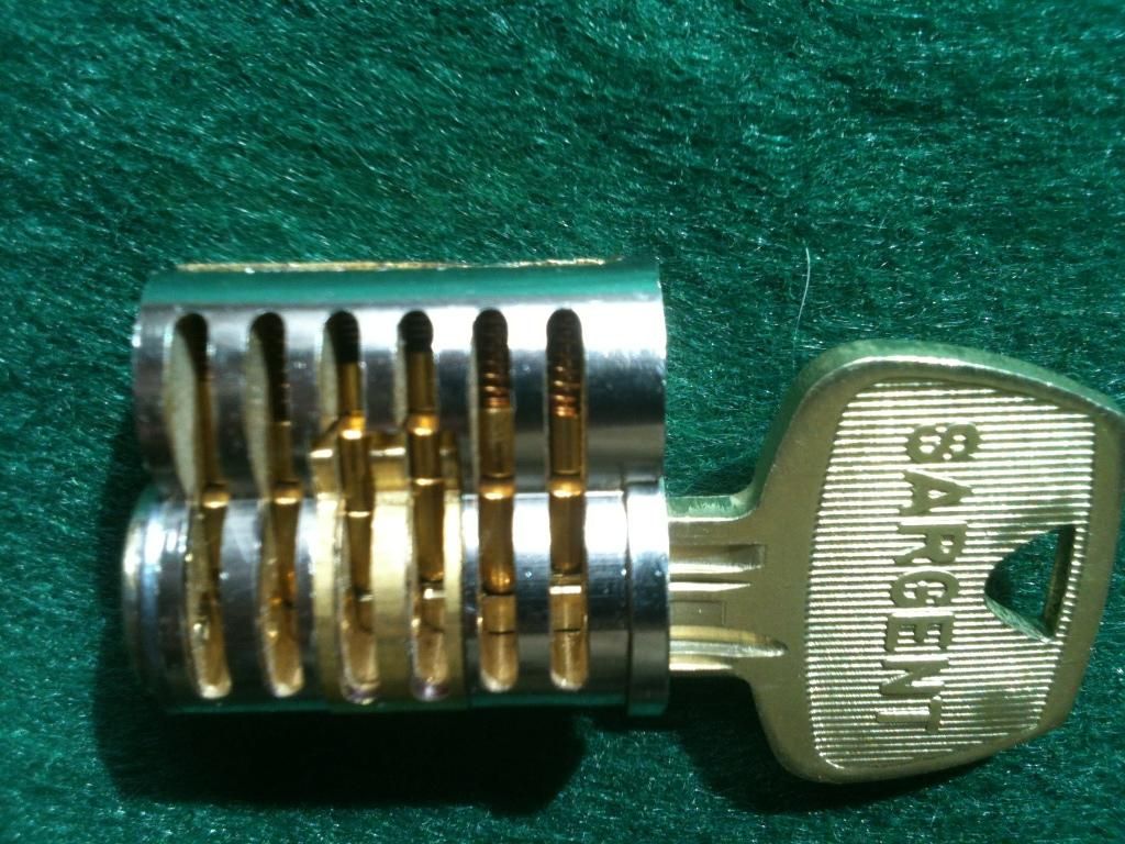
And the control key turned to retract the control lug (the brass section in the middle), allowing the core to be removed.
Hope you like them!
Gordon