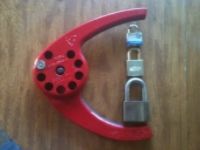
This is the model 0883, which is the little brother to the large model 0881, best known as the railroad padlocks. These are smaller in every respect, with a much smaller shackle and even the key is far smaller. This model uses the same keyway and can use the same blanks as the Abloy Classic locks. The first one I got actually had an Abloy Classic key. For this one, I got my grubby little paws on some S&G blanks for this baby. But first, to disassemble.
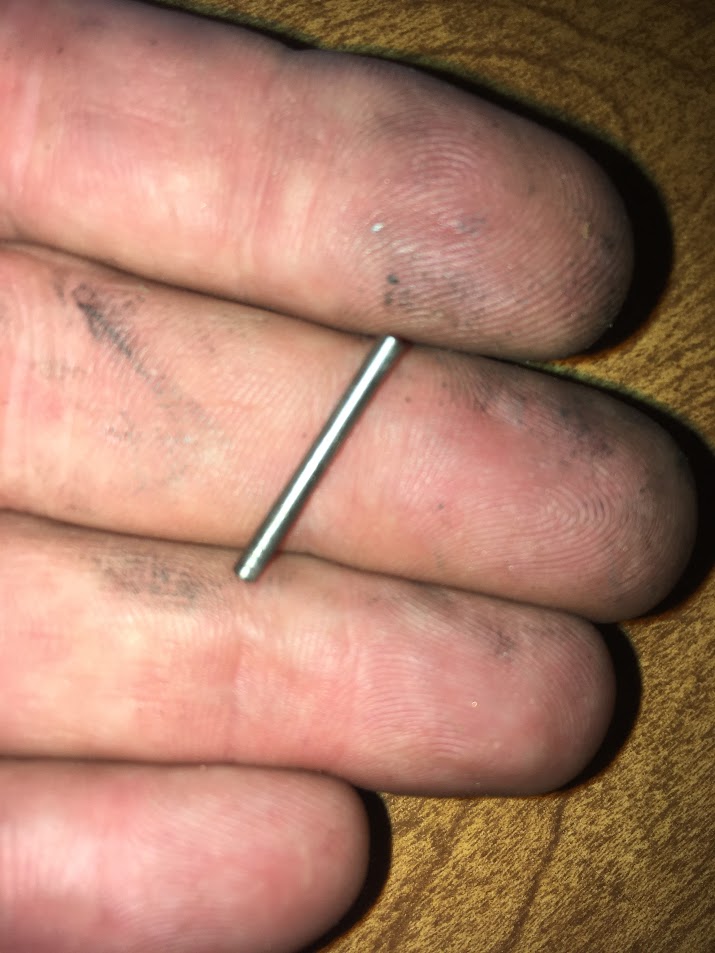
Open the lock since the shackle must be lifted to access the disassembly set screw. The set screw is accessed through this hole on the top side of the lock on the toe side of the shackle.

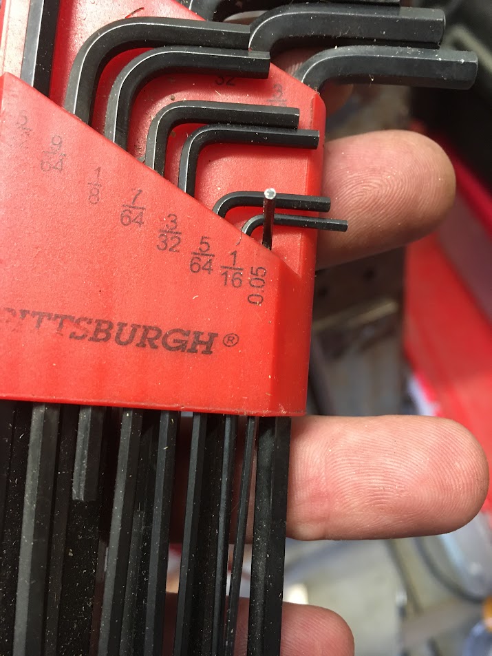
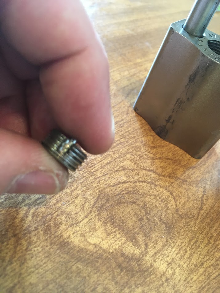
You will use a .05" allen screw to back off the set screw.
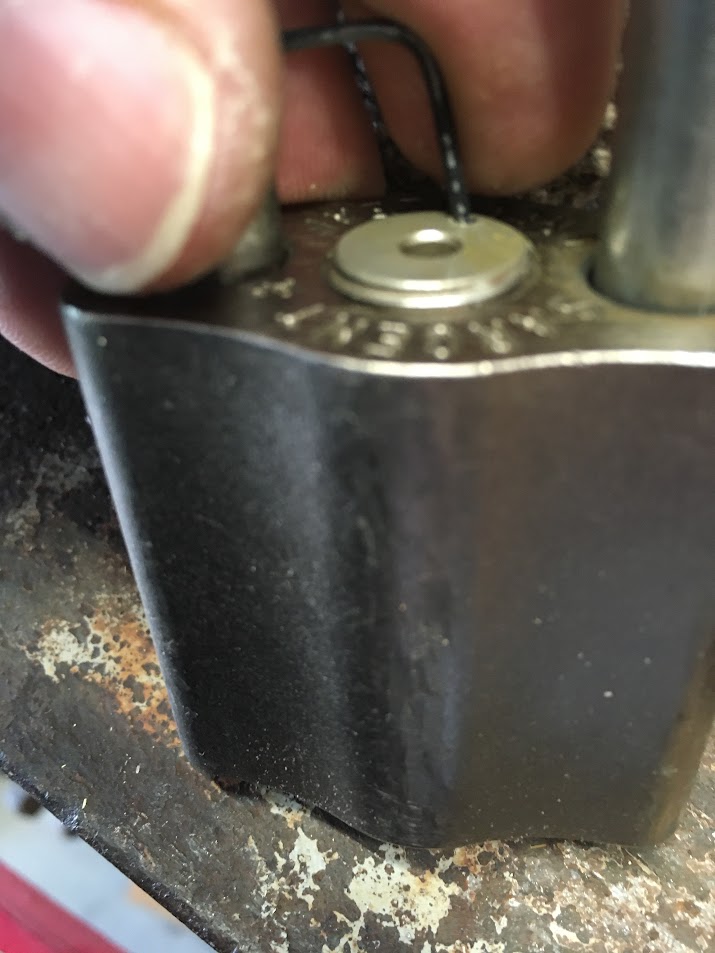
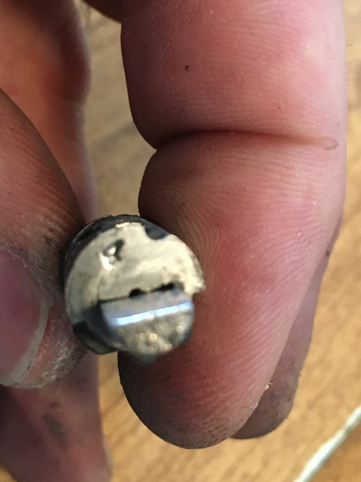
Once the set screw is backed off or removed (in this case, I removed it), the cylinder cap on the top of the padlock body needs to be unscrewed.

It will no doubt be stuck a bit, so use a very small hammer or mallet to tap an allen screw that is fitted into the hole in the cap. Keep rotating it until the cap can be removed.

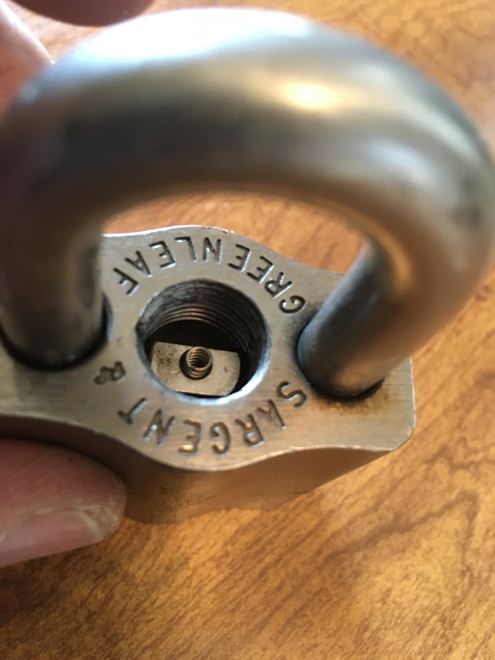
The bottom of the cap has a peg that fits inside a spring shown soon.
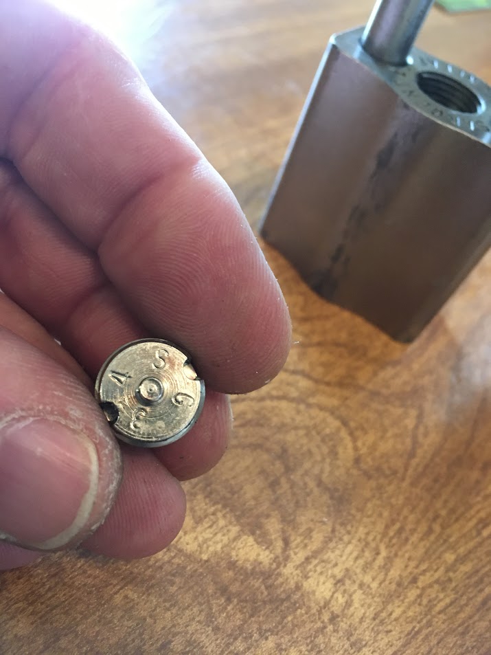
Two sides of the cap have grooves in them where the set screw fits to keep the cap from being spun off.
Looking into the hole when the cap is removed, you see the spring mentioned above set into a hole in the actuator. Note the actuator orientation in your lock - that raised part in the middle is offset. When in the unlocked position, the side that is more heavily cut away will face the shackle toe.
For disassembly, I am using a generic Abloy Classic key blank.

Make sure that the key has turned the actuator to the fully unlocked position. Ignore that I am using a blank in this picture. I had my reasons.

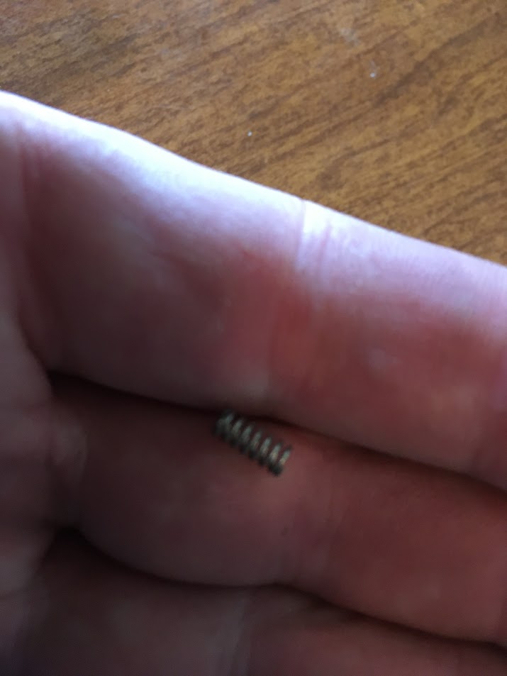
Remove the spring from the actuator.
lift out the actuator.

Here you can see that offset center raised area of the actuator. That is so the locking balls (which are different sizes, too) can be retracted the correct distance to allow the shackle to be raised without coming all the way out of the lock.

One side of the actuator. That groove in the bottom of the actuator allows the actuator to mate up with the cylinder housing below.


Looking back in the lock body, you see the cylinder housing.

Tip the lock to each side, shaking the locking ball into the opening and remove. Remember which locking ball goes in which side since they are different sizes.


At this time, you can remove the shackle. There is no shackle spring. But I took the pictures with the shackle still installed, so that is how you will see the pics.
Turn the key to the locked position and remove the key. If you have a blank, use one. If not, a straight wire coat hanger will work fine. Turn the lock upside down and use the key blank or wire to push the cylinder housing out of the lock body. You can see the cylinder housing starting to poke out of the lock body at the bottom of the picture inside the shackle. (That is why I left the shackle in place for these pics - you can see orientation of the lock body).
Remove the blank as the cylinder housing slides down since the key bow won't fit inside the keyway hole. Keep tapping the lock upside down to get out the cylinder.

And out she falls!

Here is the cylinder housing. The bare groove in the side of the housing has a matching one on the opposite side. These are where the two sidebars fit, one on each side.


Now I am removing the shackle that could have been removed above.

Here a key blank comes in very handy. Not essential, but keeps things oriented well. Remove the discs and spacers, keeping them in order.

On one side of the stack, you will see the narrow individual gates. On the other side, the wide gates that prevent the discs from being turned too far.

At the tip of the key is the first disc. Note the number on the disc. In this case, 4. Keep track of which way each disc is facing which way and where the gates are located.
Next comes a spacer. Note that on the triangular shaped spacers, the corner with a gate in it faces the wide part of the discs.

The second disc is a B. Spacer. Third is a 3. Spacer, followed by 2, 1 and another 3.
Here are all the parts (except for the set screw which I forgot to include in the pic.

The lock body, discs and spacers:

The rest of the parts:

Now am going to show the discs in pairs. A 1 disc flips over to become a 4 disc!

B flips to become a D.


And a 2 becomes a 3.


Now to make a key. Lay the key blank along the housing with the discs and spacers installed. Use a fine point Sharpie marker to mark where the center of each spacer is located.

Cut the bitting as required for each place, testing the key in the cylinder as needed to be sure the gates line up with the sidebars. Your key will end up like this one, except your bitting most likely will be different.

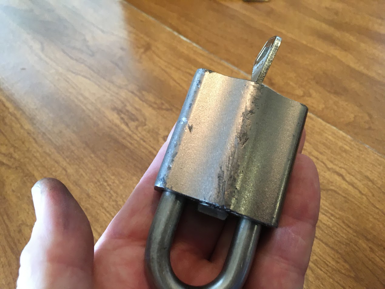
Reassemble the lock and test your key.

If correct, the key will turn just over a half turn.

Woo Hoo!!!

Hope this was worthwhile for you.
Comments are welcome
Corrections or comments made
Haiku should be used.
Gordon