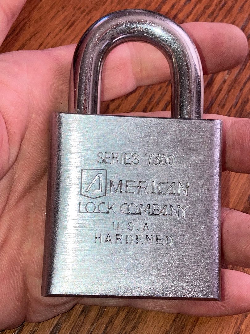
This is for any of the American Lock tubular padlocks in the 7000 series. Let me start by saying that the core of this padlock. DOES NOT come apart like most other tubular locks, where you drill or extract a pin in the side of the core to disassemble. However, basic disassembly to remove the core is the same as most modern American padlocks.
Unlock the padlock and remove the phillips screw that holds the trap door on the bottom.
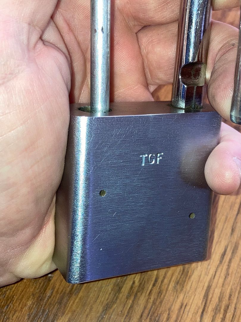
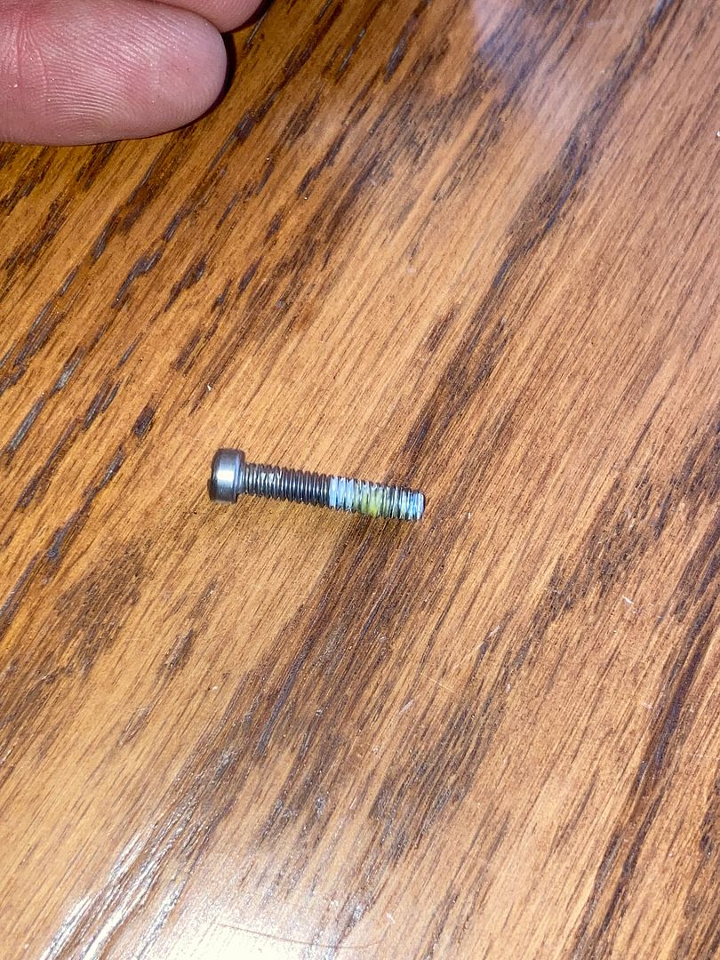
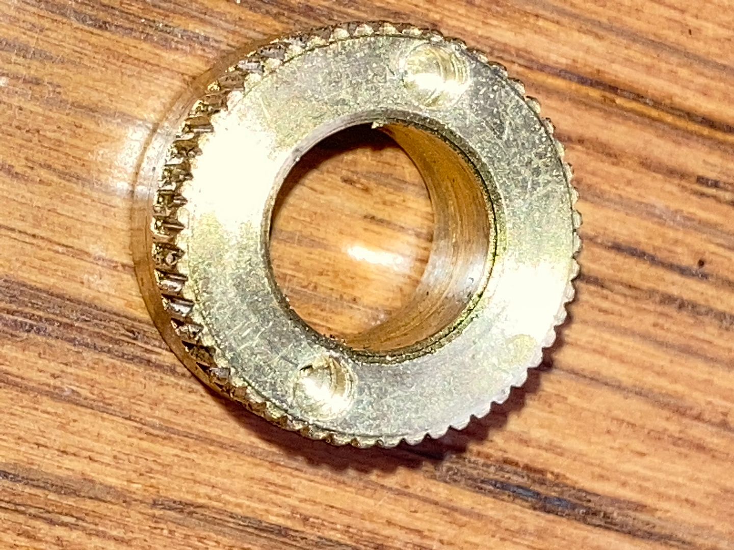
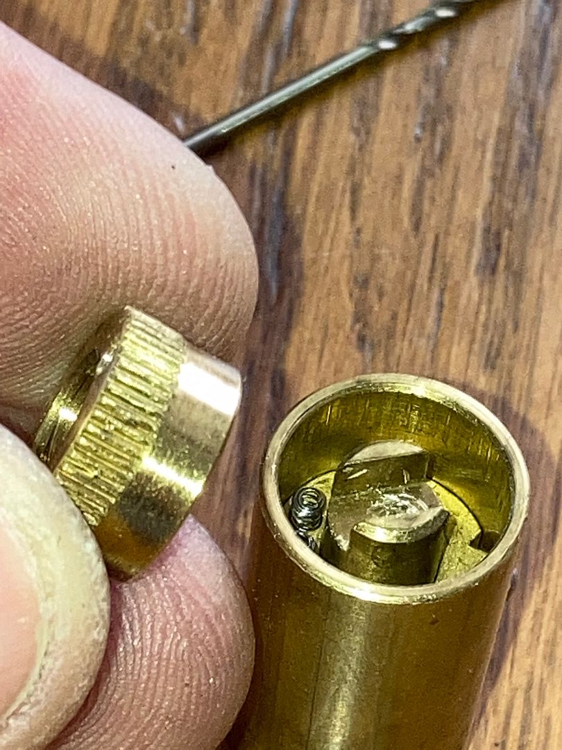
Remove the sex nut and trap door.
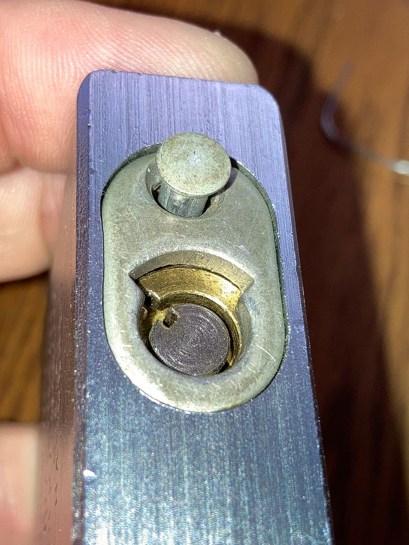
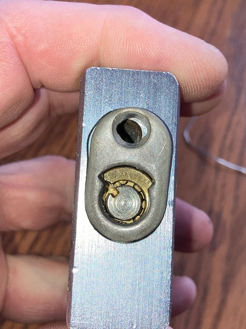
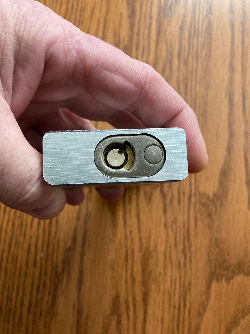
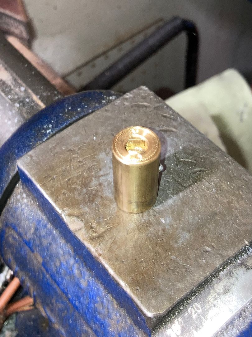
Now you can see the core in the padlock body without the trap door.
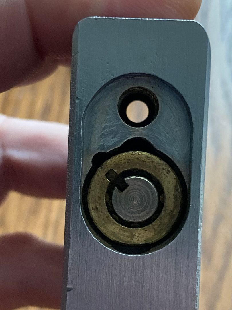
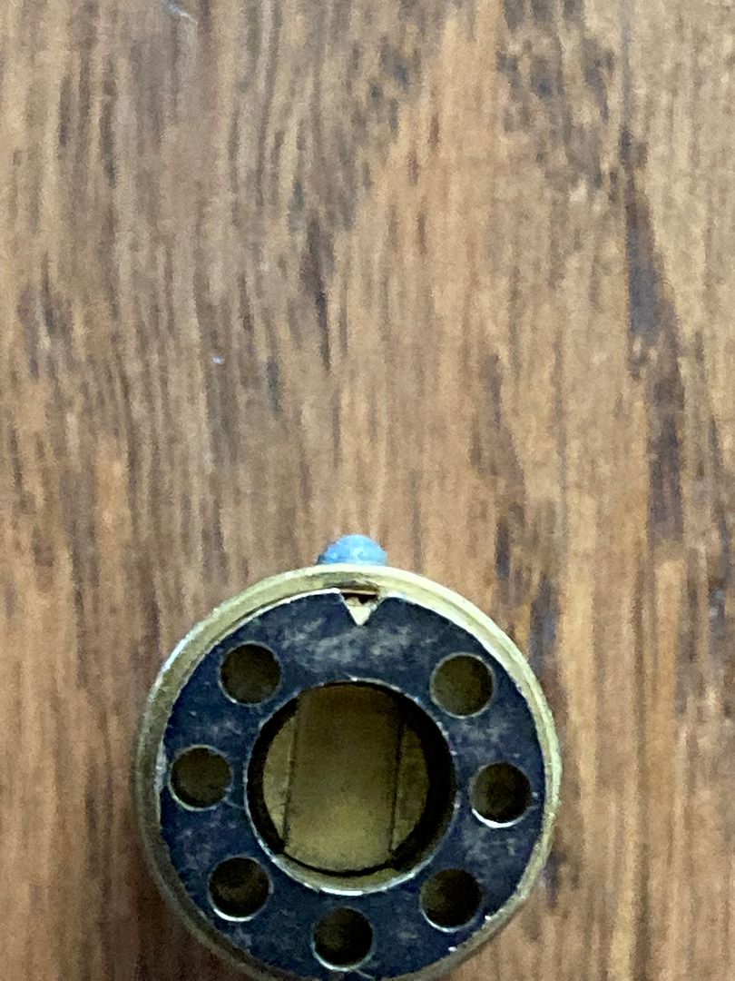
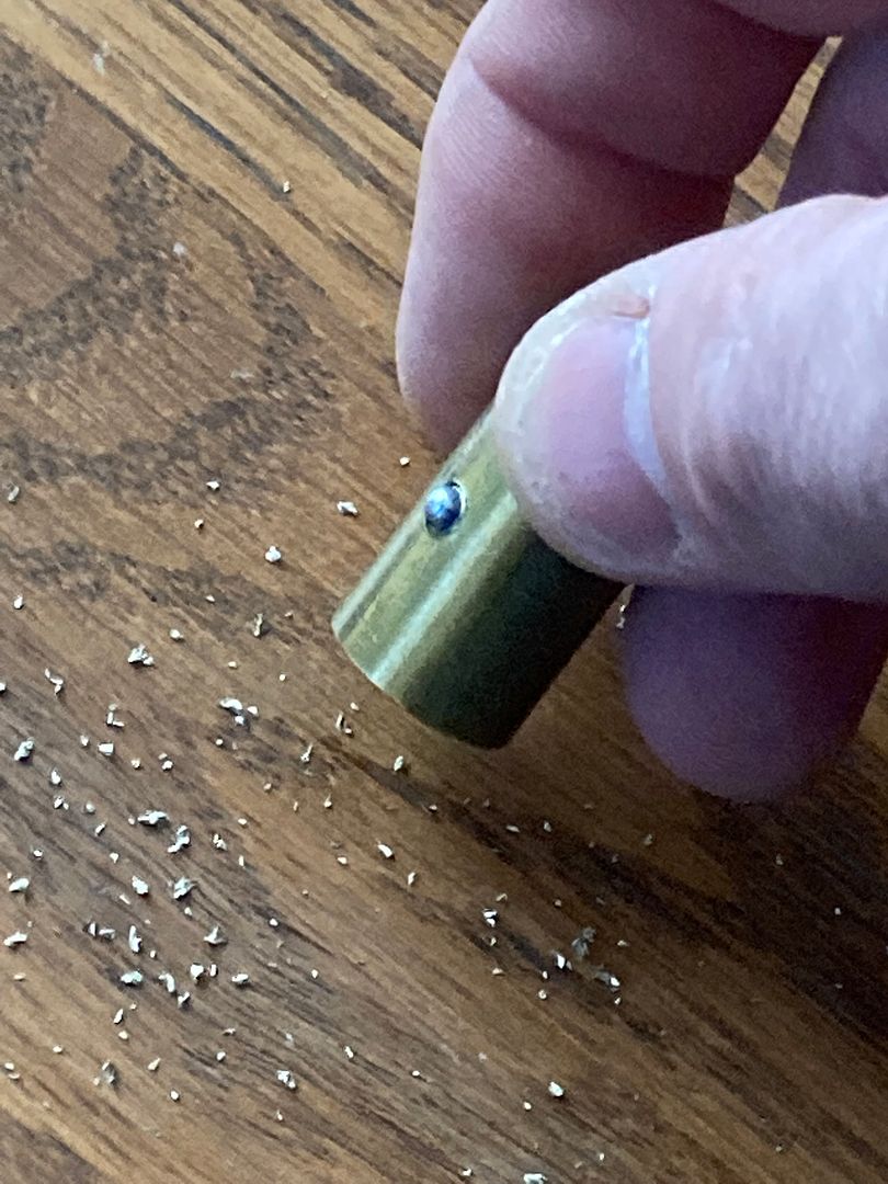
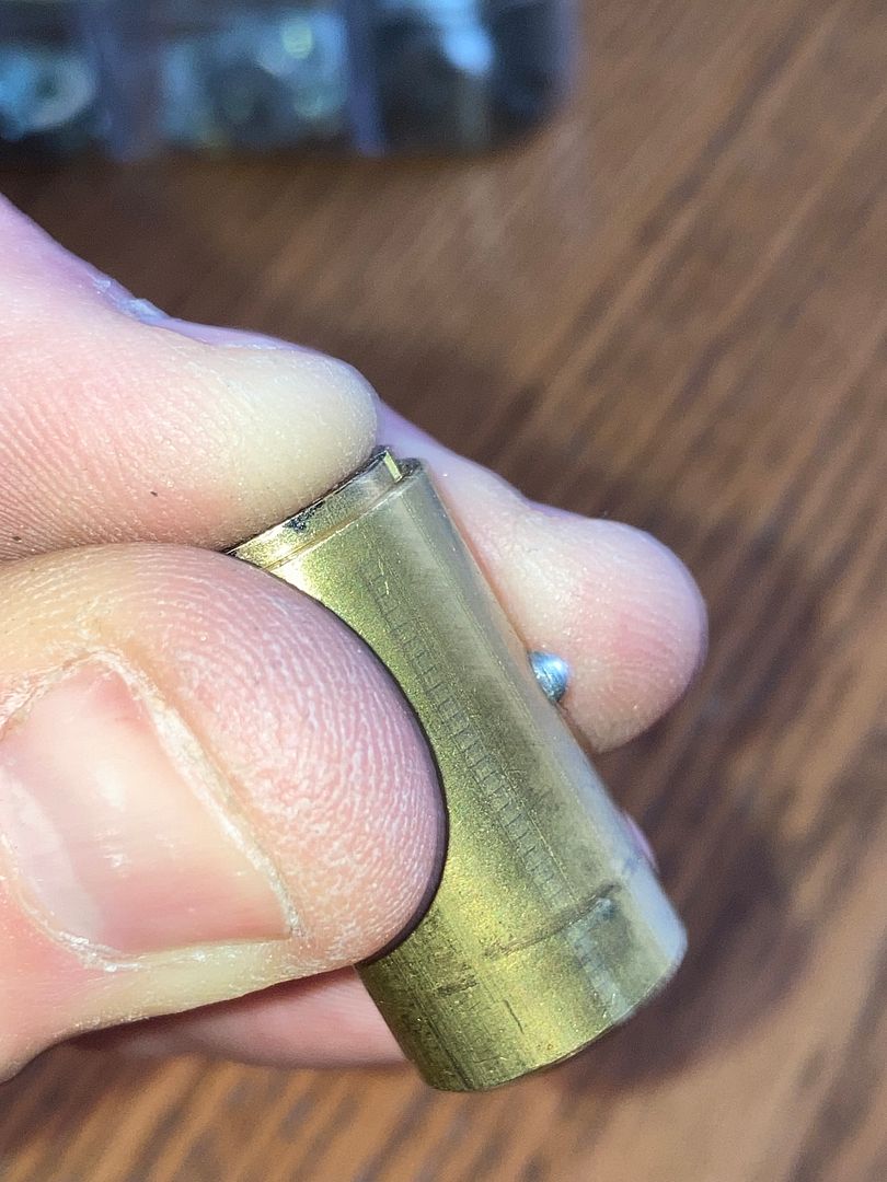
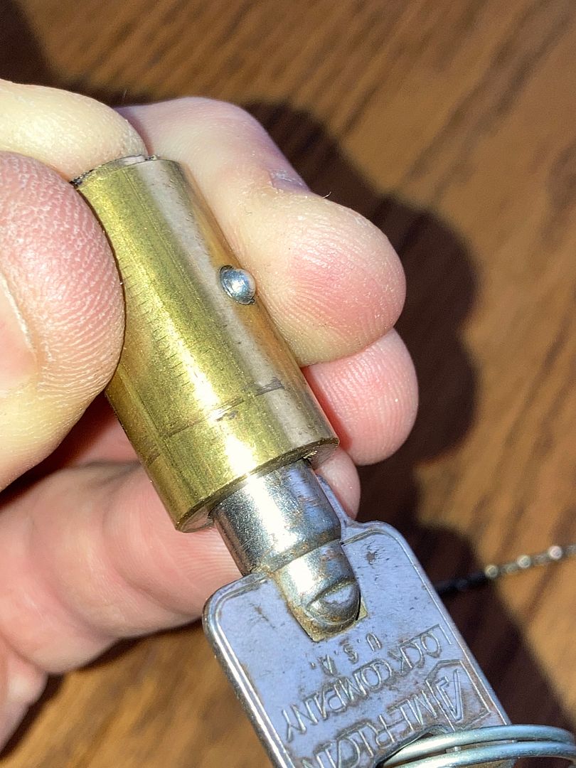
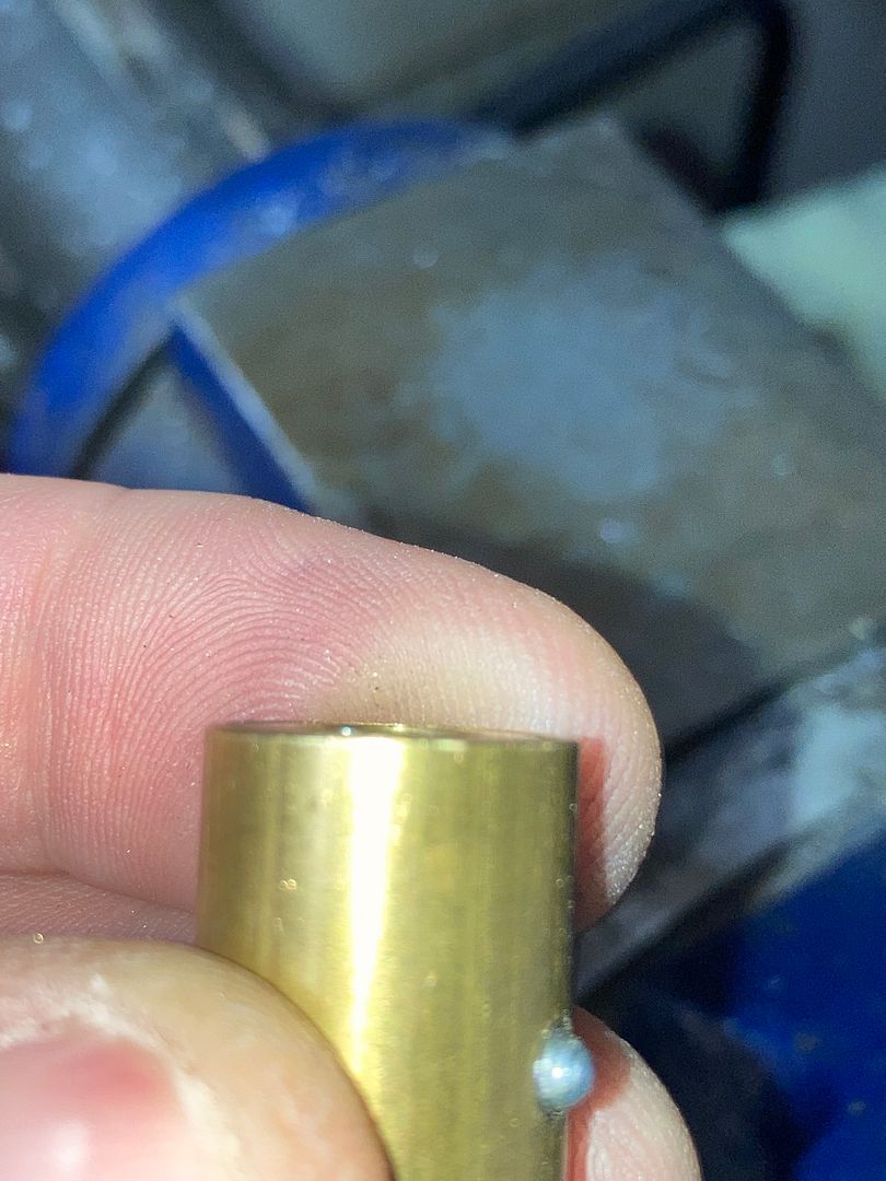
Tip the padlock downwards, allowing the core to slide out of the body. As you so, note that the steel pin in the side of the core is aligned with the left groove , not the center groove.
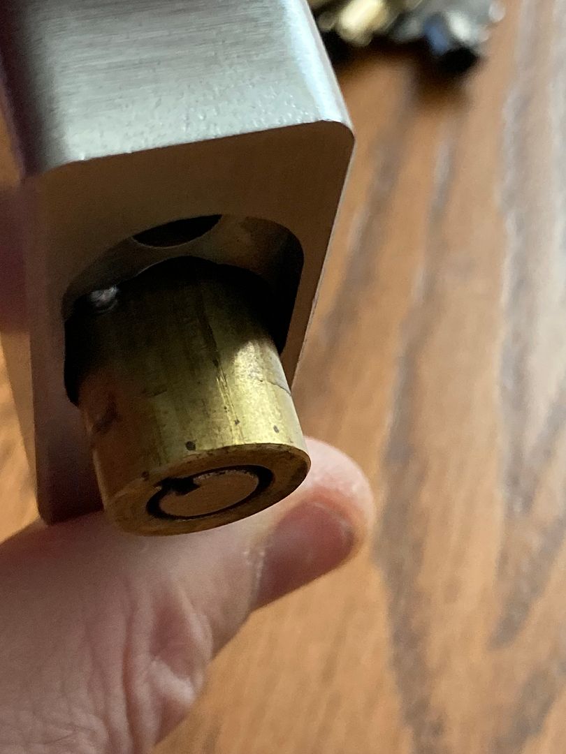
Here is the removed core.
Here the driver is set into the back of the tubular core. Pay attention to the angle related to the steel pin on the side of the core.
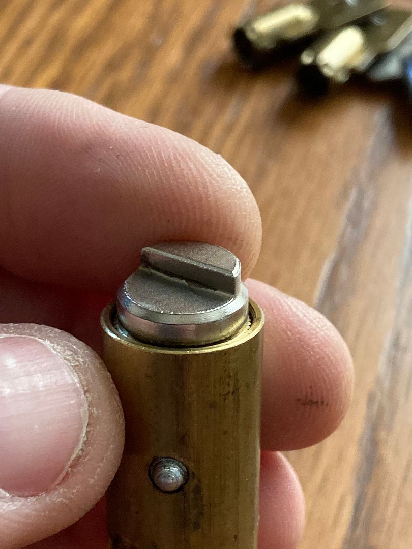
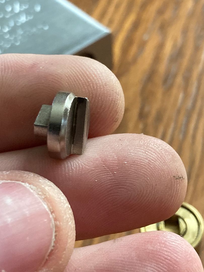
Here are both sides of the driver.
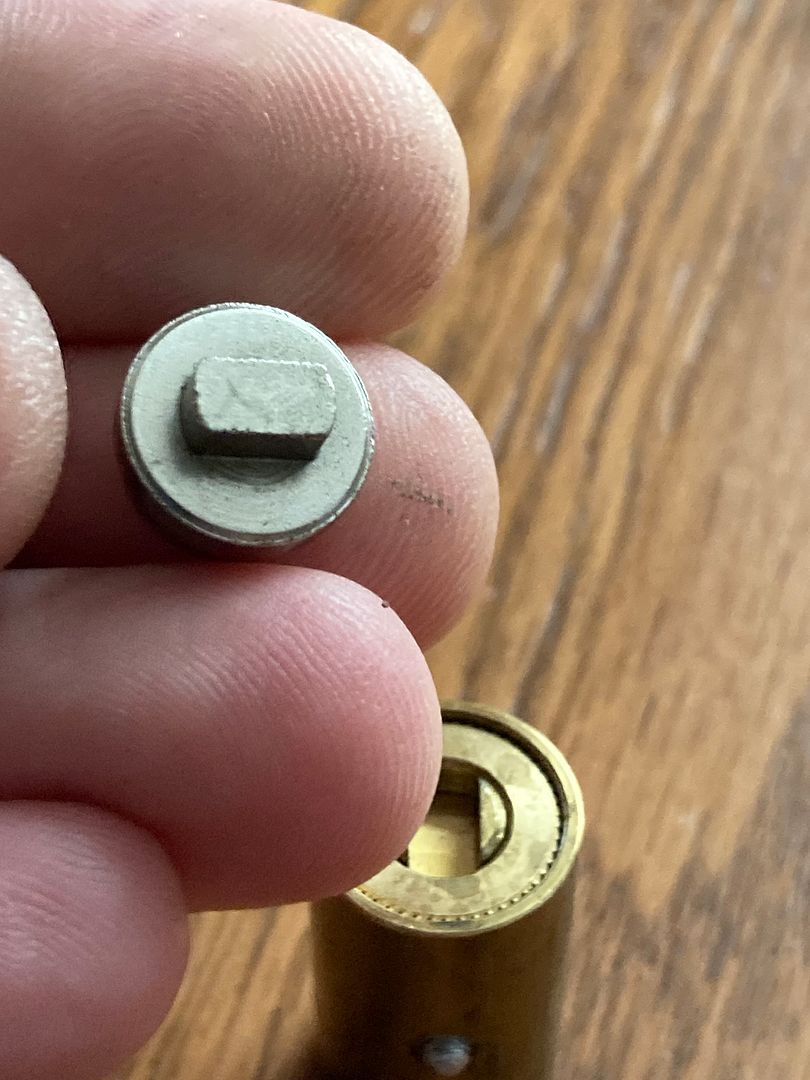
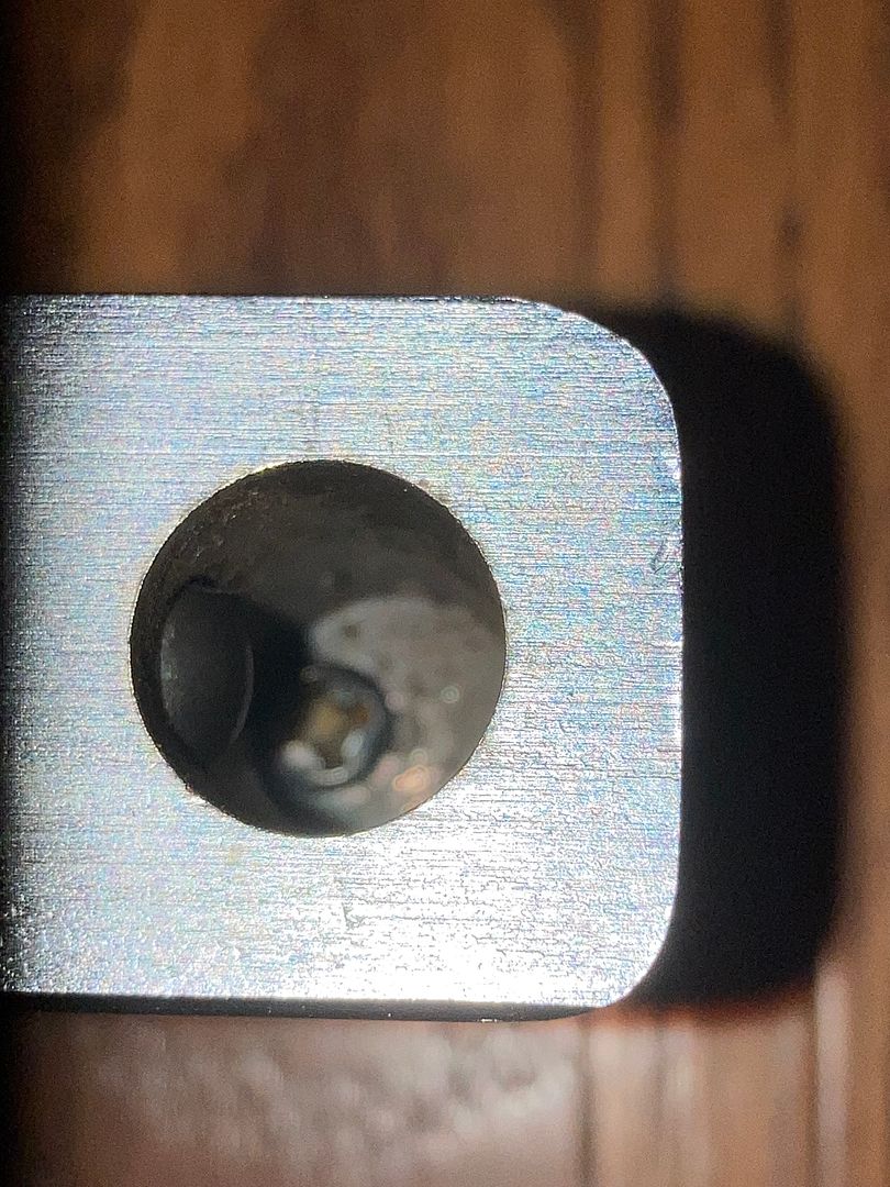
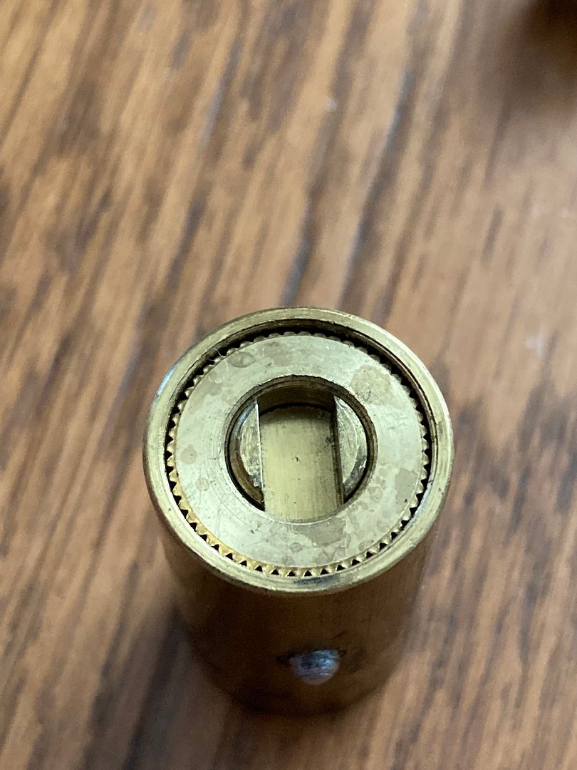
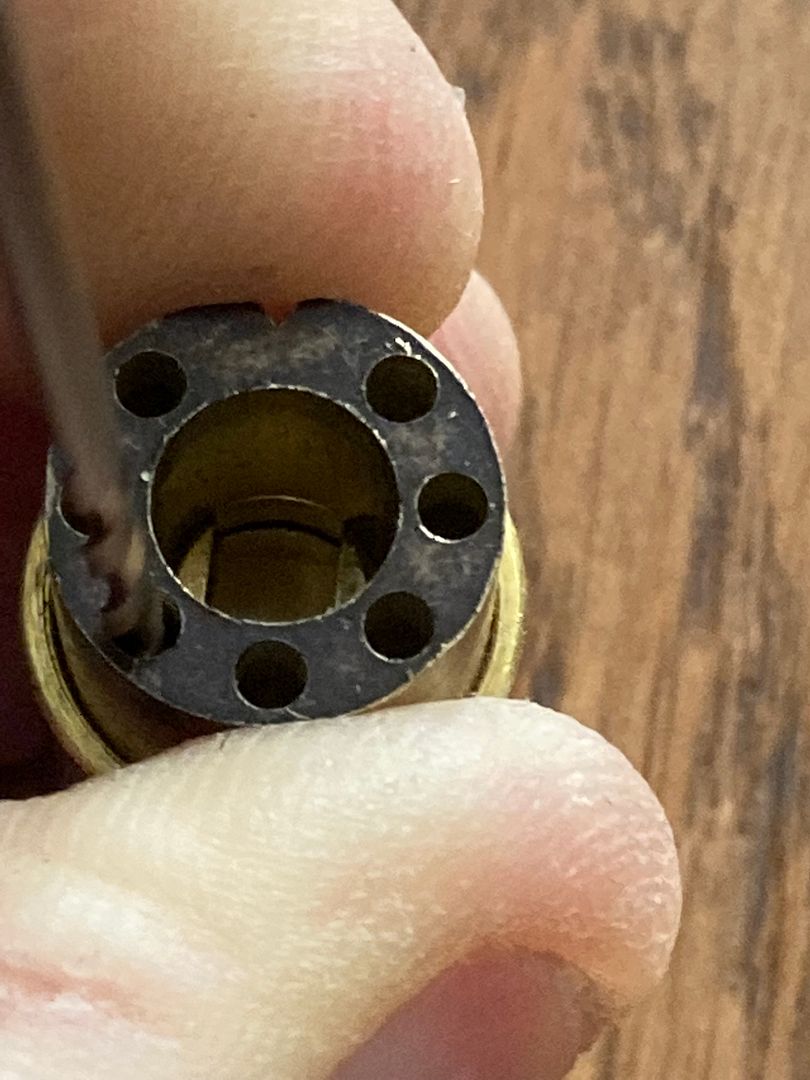
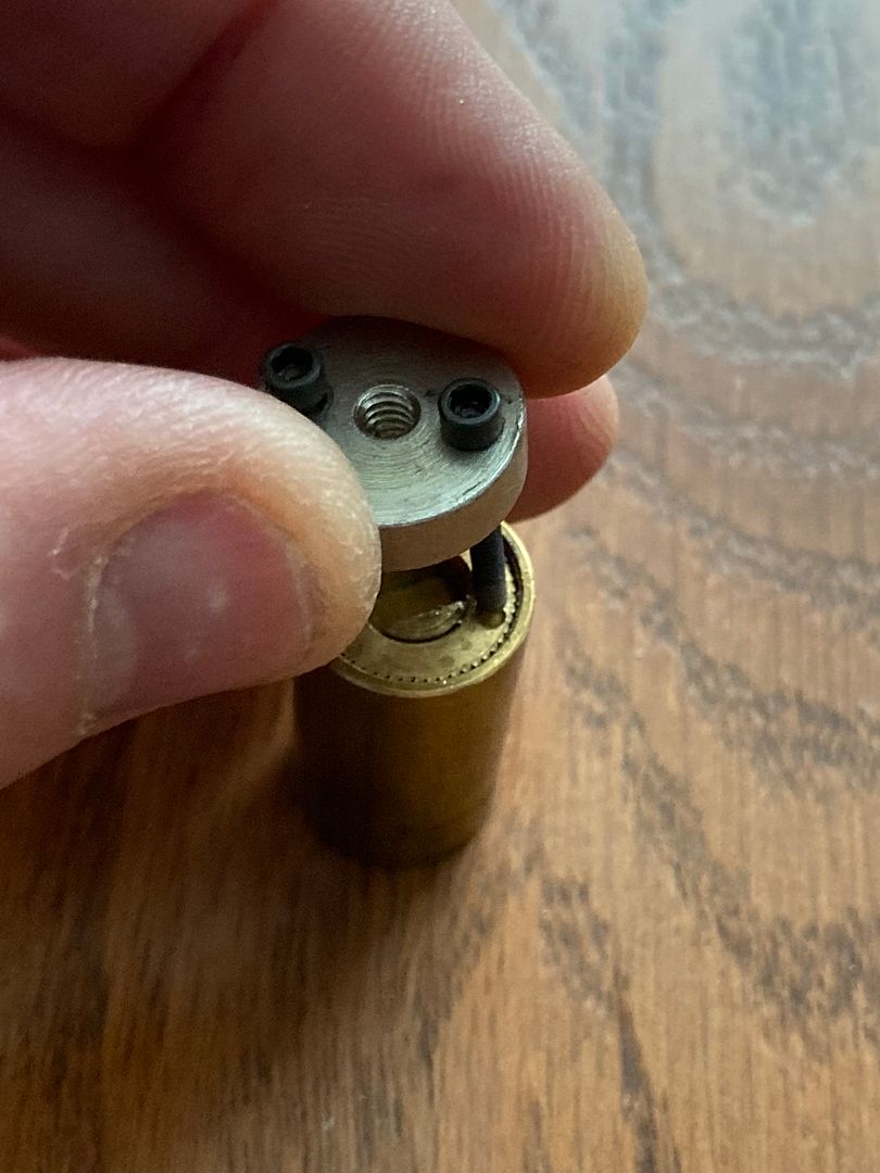
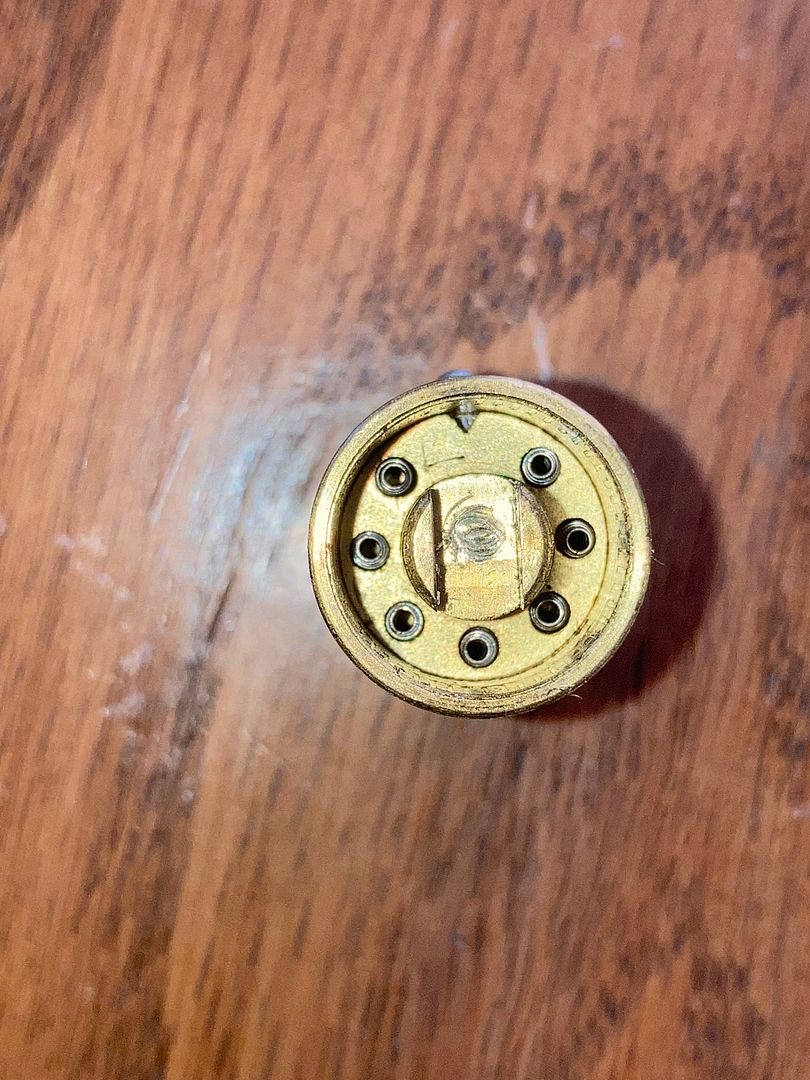
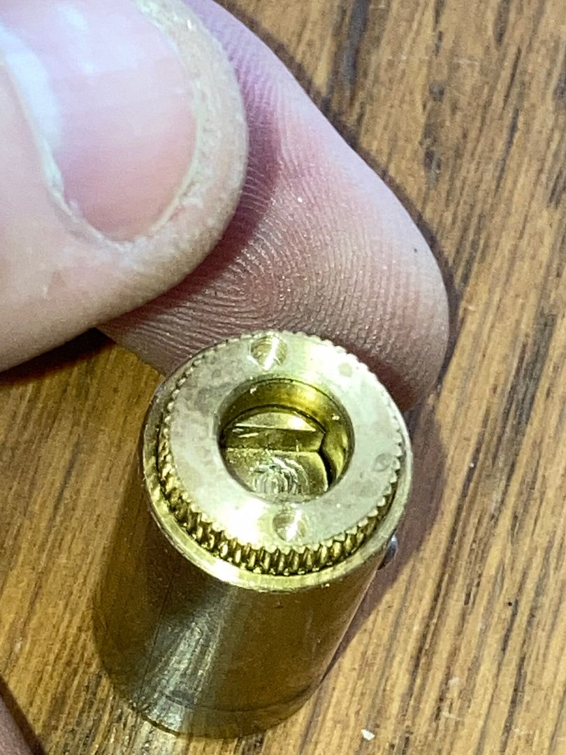
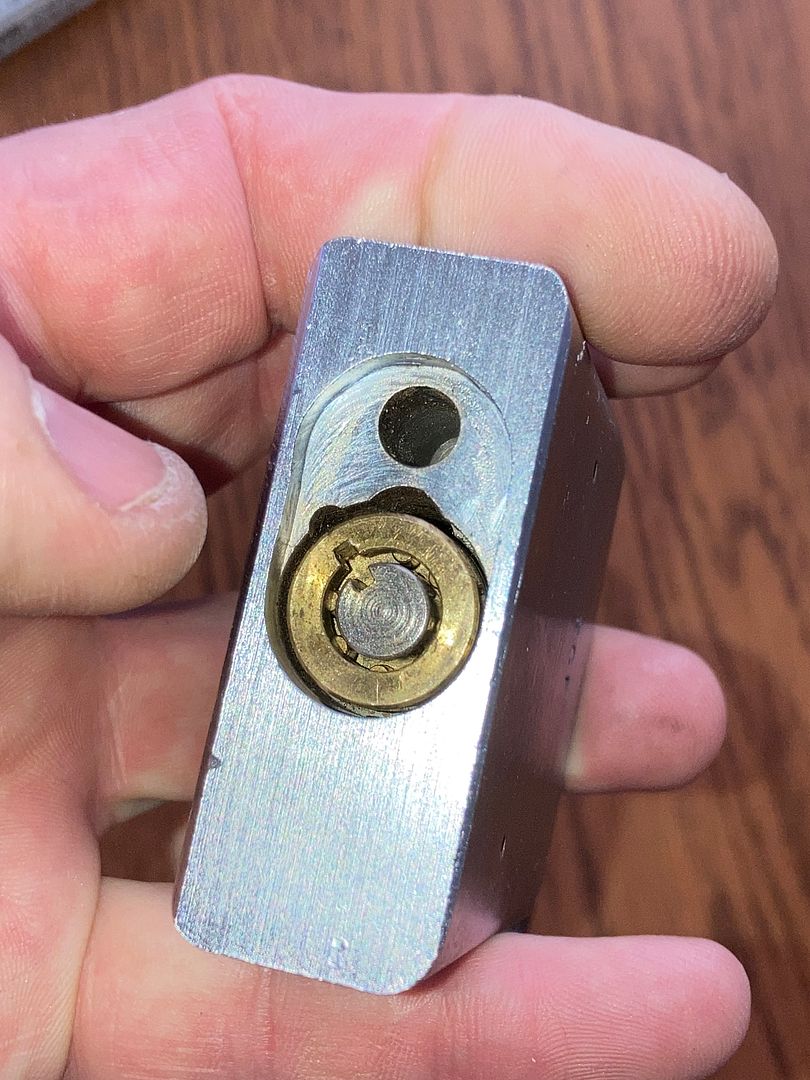
And the back of the core with the driver removed. We will be dealing with this shortly.
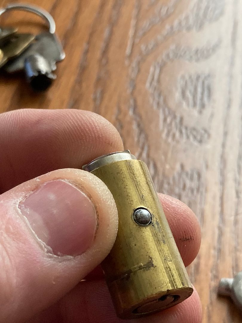
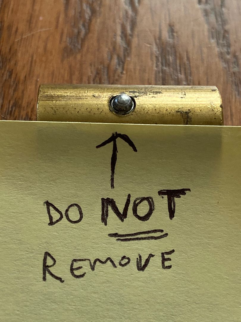
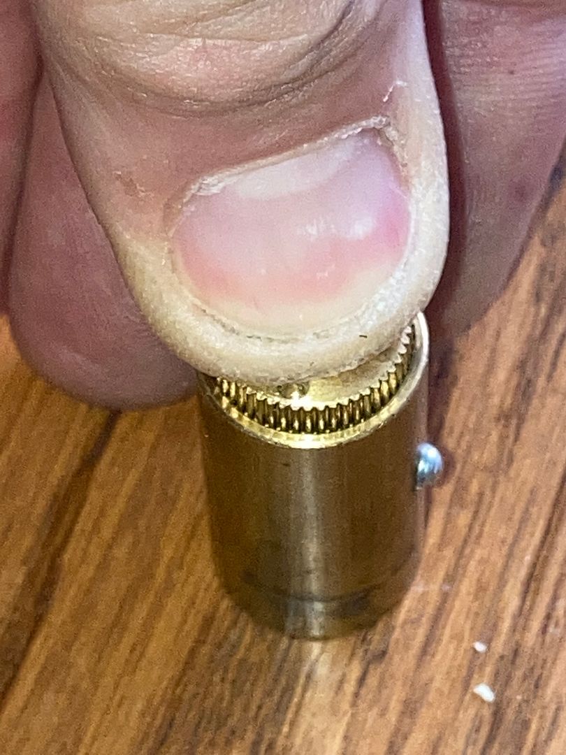
On most tubular locks, you would remove this pin, either by drilling or using a screw to remove it. With the HTC2 core used in the American 7000 Series padlocks, you DO NOT attempt to remove the pin. First, you won't be able to. Second, it is not how this core is serviced.
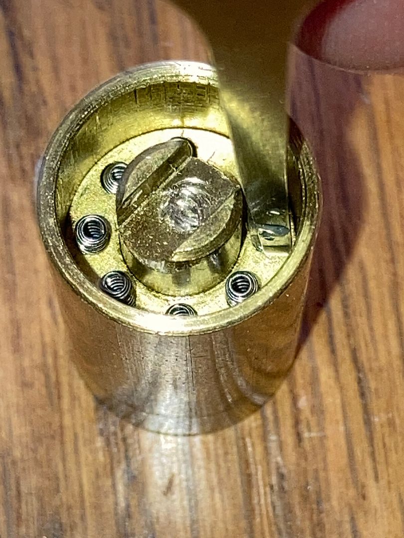
The more modern core of this lock (this particular lock is from June 1989), the back looks different because of an additional circular groove being milled in the stop spacer. That being said, the modern core comes apart for service in exactly the same way as this one. I have a few of the cores on order that would have the new stop spacer with the circular groove cut in it, but they are currently on back order. I did a few of them last week, but did not take any pics.
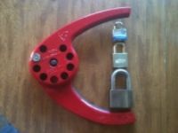
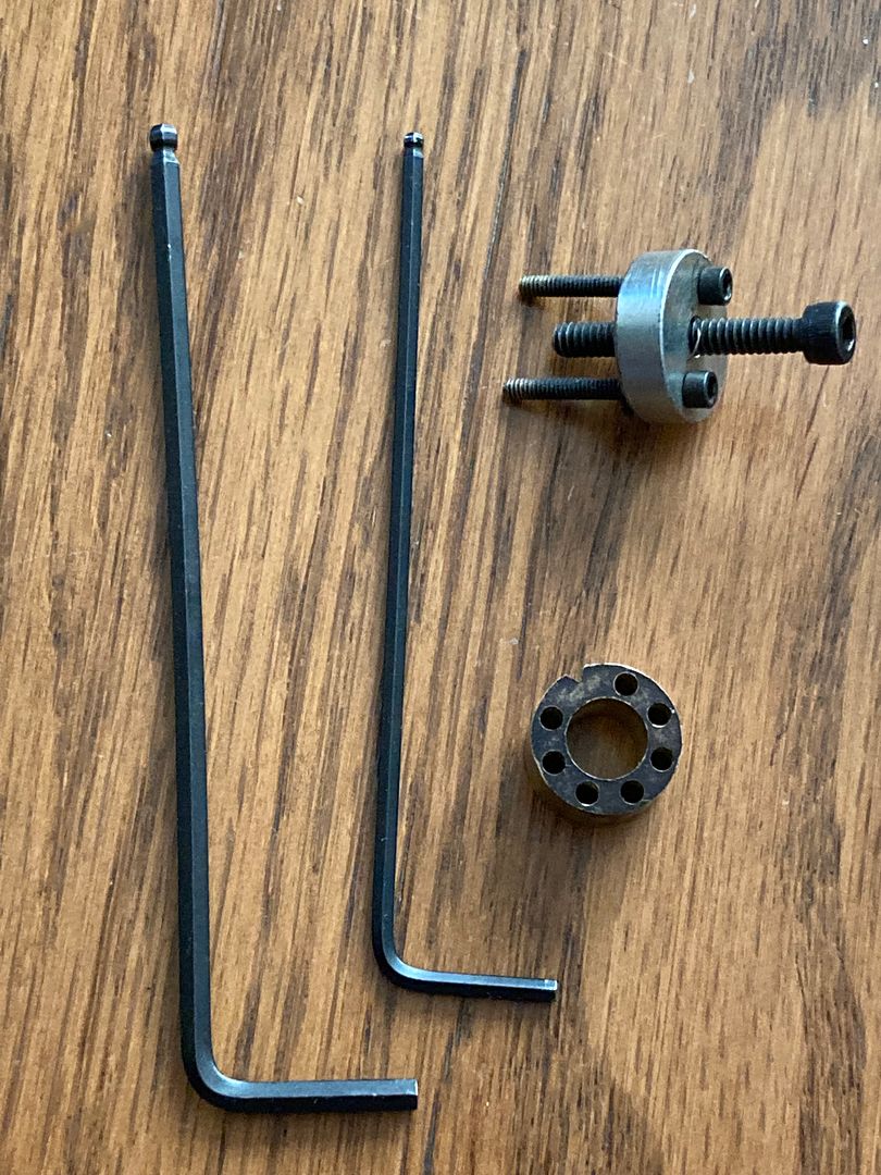
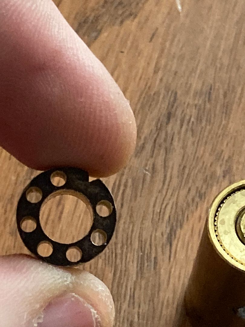
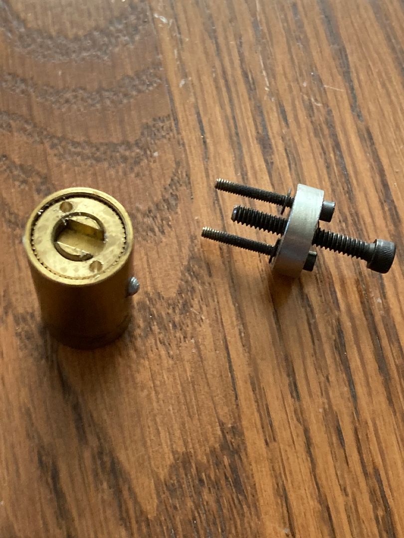
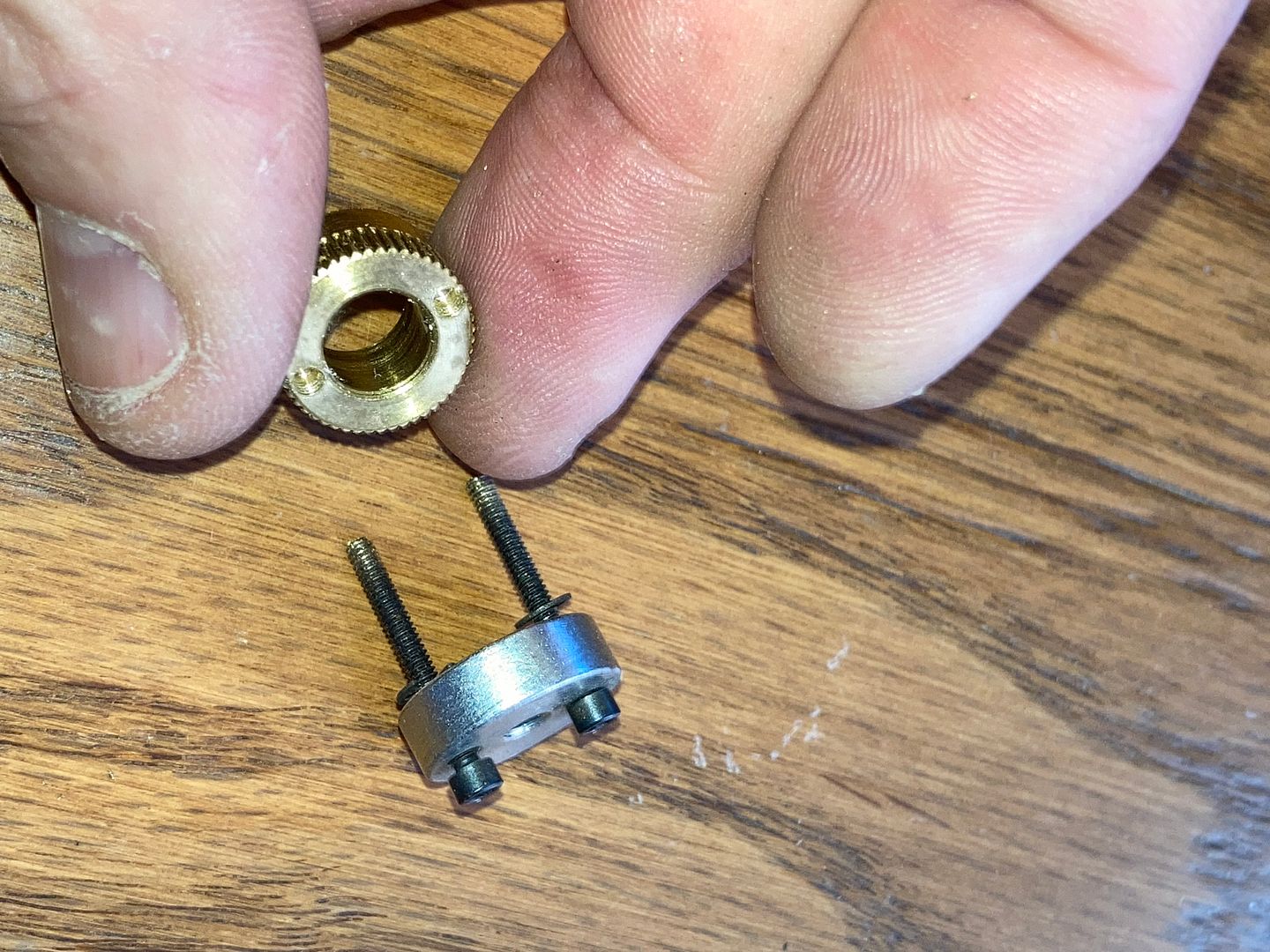
Anyway, time to take this core apart. You will need a few tools. Yes, that is indeed a tiny bolt puller. If you guys want specs so you can make one, too, let me know in the comments below. The round piece with the seven holes is a spare core shell from another core. It really helps make it easier to pin the core later.
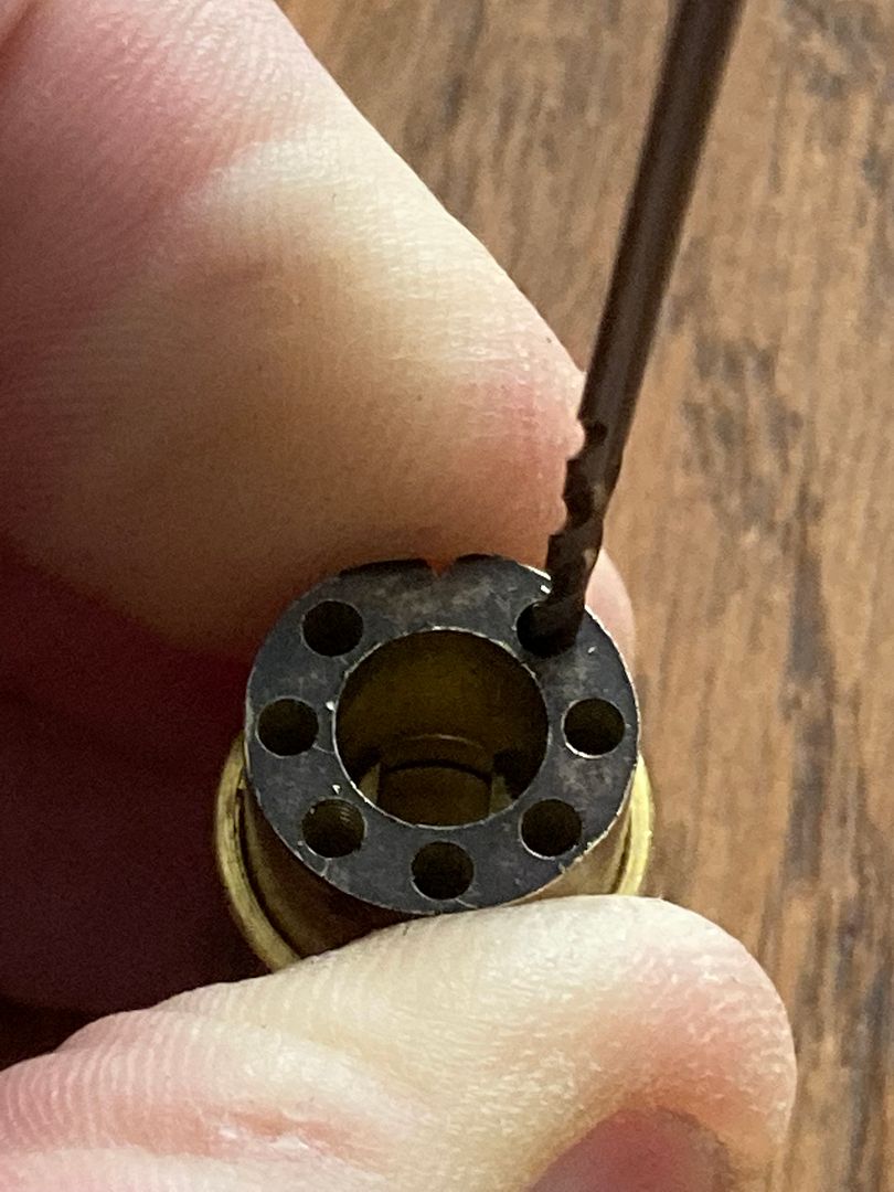
To make hole alignment easier into the stop spacer on the back of the core, place the spare shell on the back of the core...
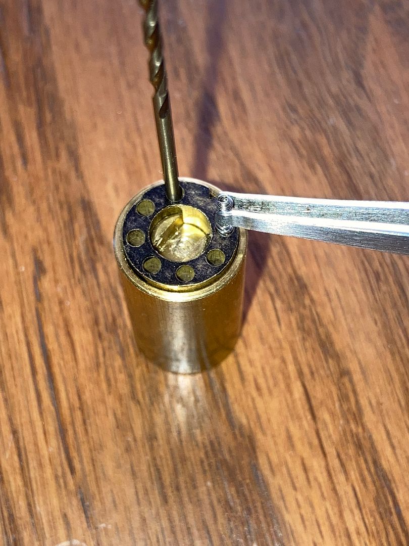
Use a drill bit (I used a number 50 drill bit) twirling it by hand in holes on opposite sides of the core, marking the back of the stop spacer.
Remove the spare shell and you can see the marks for drill spots.
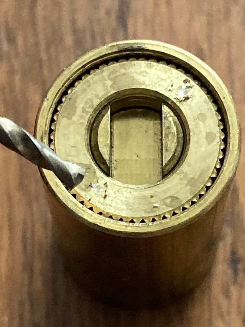
Now drill the back of the stop spacer. You do not need to drill deeply. You only need to drill about as deep as the drill bit is wide. I used a #50 drill bit for the two holes, then a 5/64" bit to chamfer the hole to make it easier to thread in the side screws from the puller.
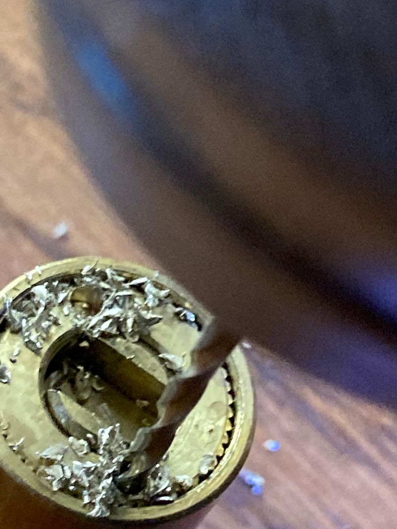
Dump out the metal shavings from drilling.
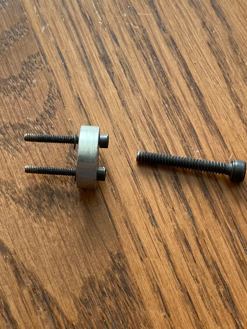
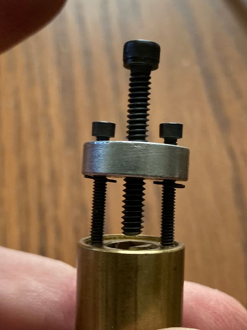
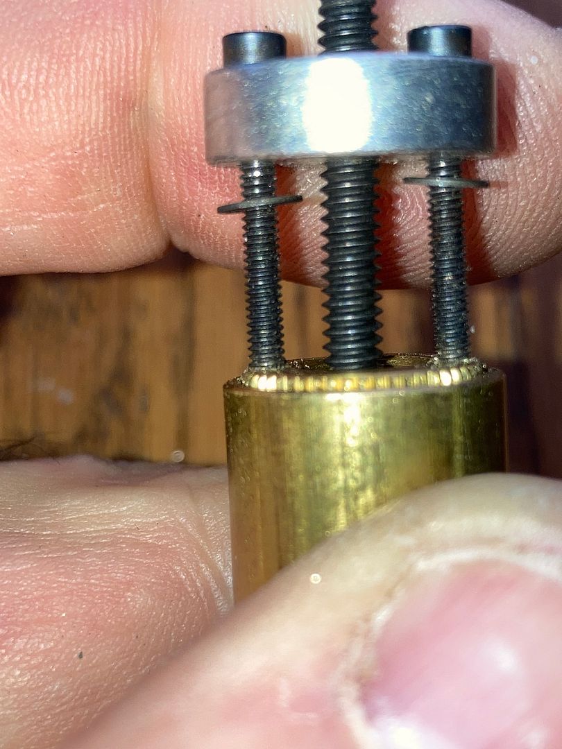
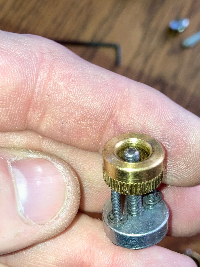
Now you are ready for the puller. This pic is a good pic to show scale of the size of the puller.
Remove the forcing screw (center screw) from the puller.
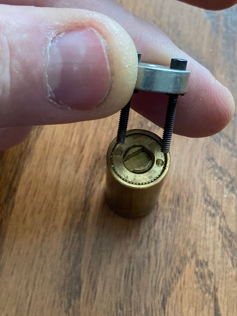
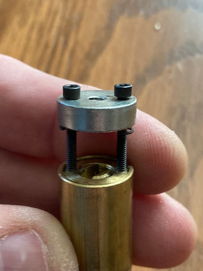
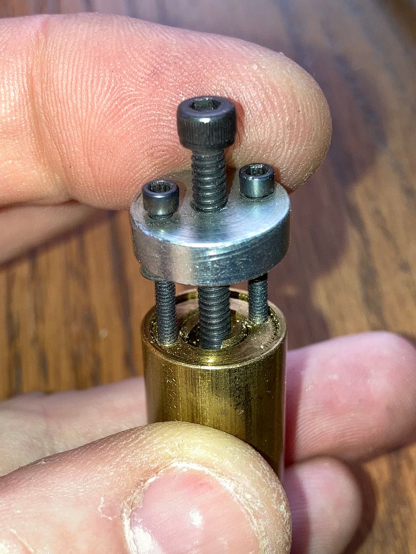
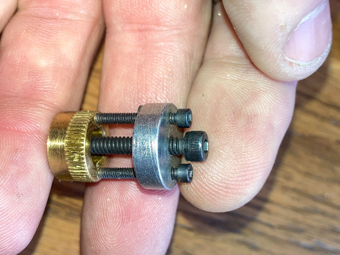
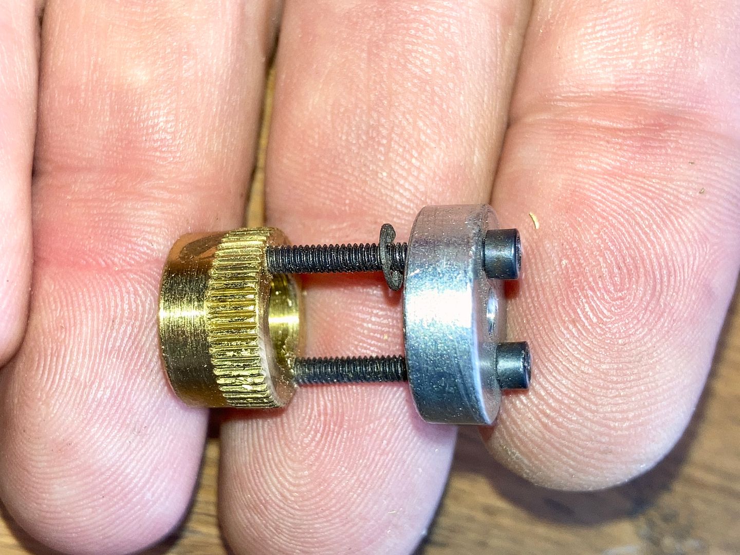
Align the puller's holding screws with the newly drilled holes in the back of the stop spacer.
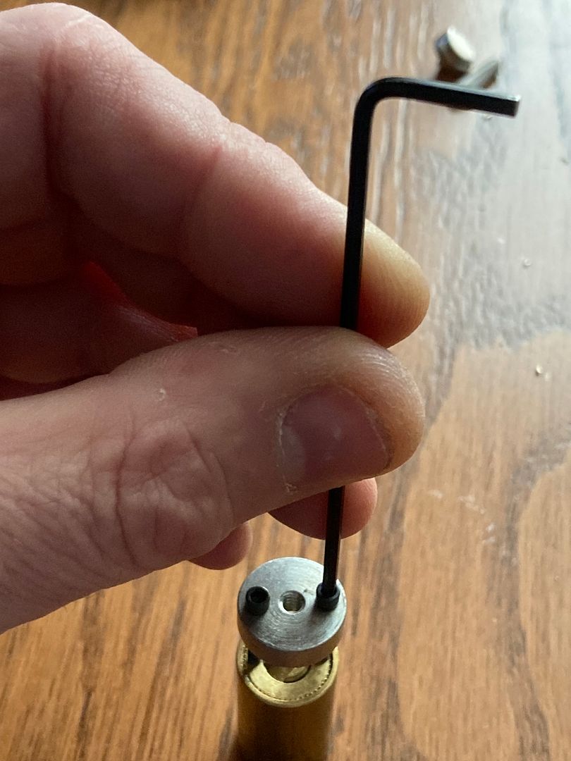
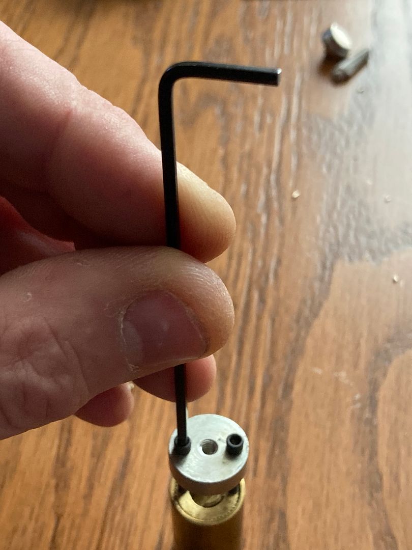
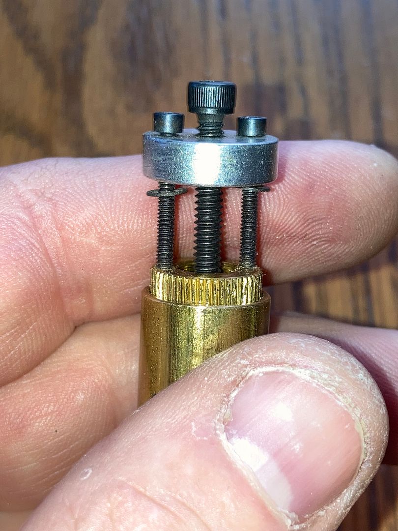
Now use the proper size allen wrench to screw the two holding bolts into the holes. Turn each bolt one full turn at a time, switching between the two bolts until both bolts have been turned at least three full turns into the stop spacer. Make sure the bolts have started gripping before you start counting! No cheating!
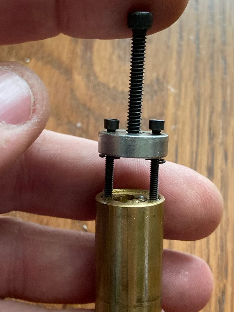
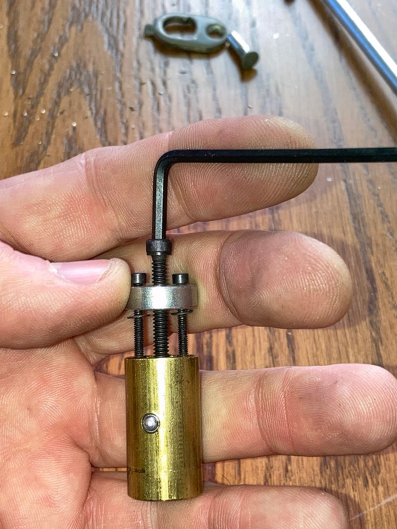
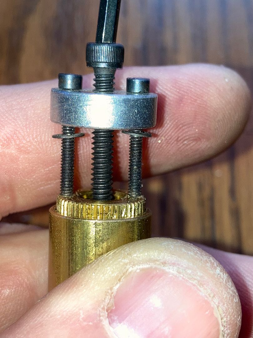
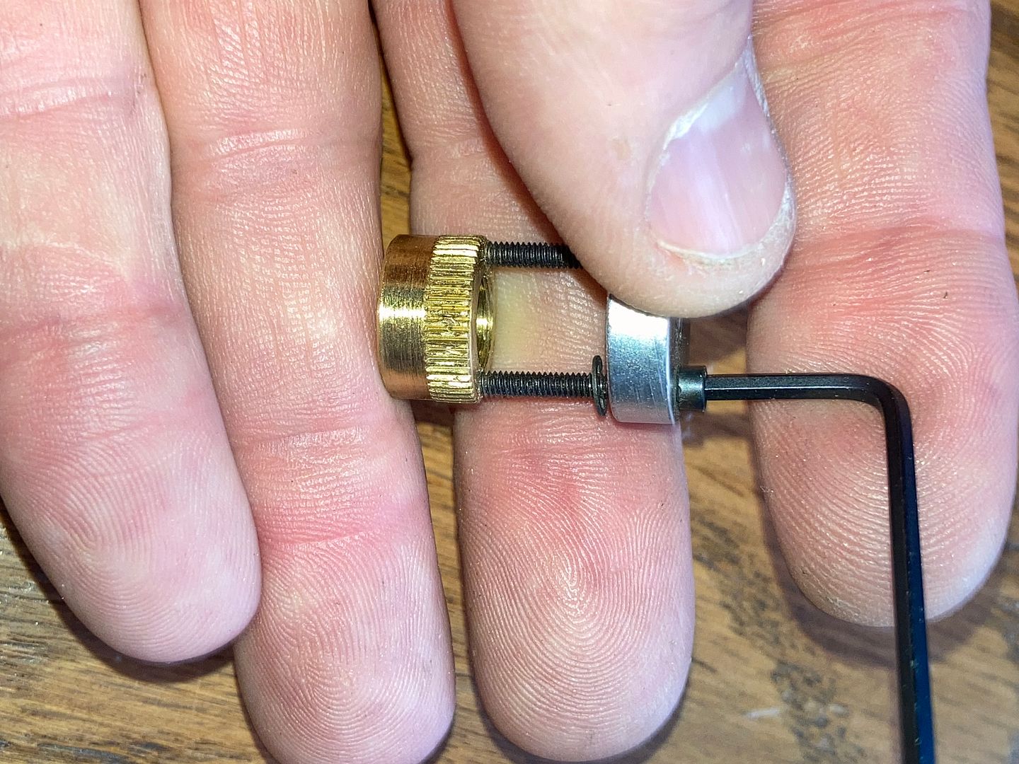
Now thread the forcing screw into the puller until it seats against the center of the core plug.
Now add the allen wrench and turn the forcing screw. This will gradually pull out the stop spacer.
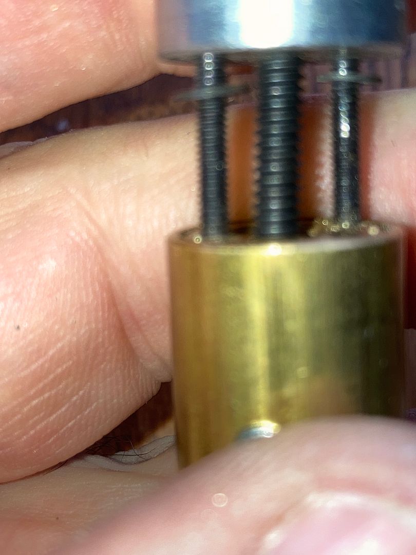
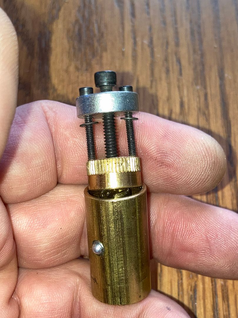
Remove the stop spacer, then the puller from the stop spacer.
Here is the stop spacer with the newly drilled holes. It is completely reusable! Will show the complex reinstallation method once I have showed how to repin the core.
Now if you look in the back of the core with the stop spacer removed, you can see the shell, springs and pin channels.
You will notice that the pin channels are actually pretty far down. With the plug stem sticking up, it is a reach down into a channel to fit pins and springs into the proper pin channels, even with tweezers. If you have thicker tweezers, good luck.
There is an easier way!!! Remember the spare shell we used to align the drill bits for the holes? Put that baby back in.
Now the pin channels reach up past the top of the core!
I find it easiest to drop the back of a drill bit into one of the holes of the extra shell, aligning all the pin channels. Then you can drop in the key pins, driver pins and springs.
Before closing up the core, be sure you should test the key to be sure it is working. Pull the spare shell up slightly (to clear the springs), rotate it slightly so the pin channels do not line up, then press it down so the springs are compressed.
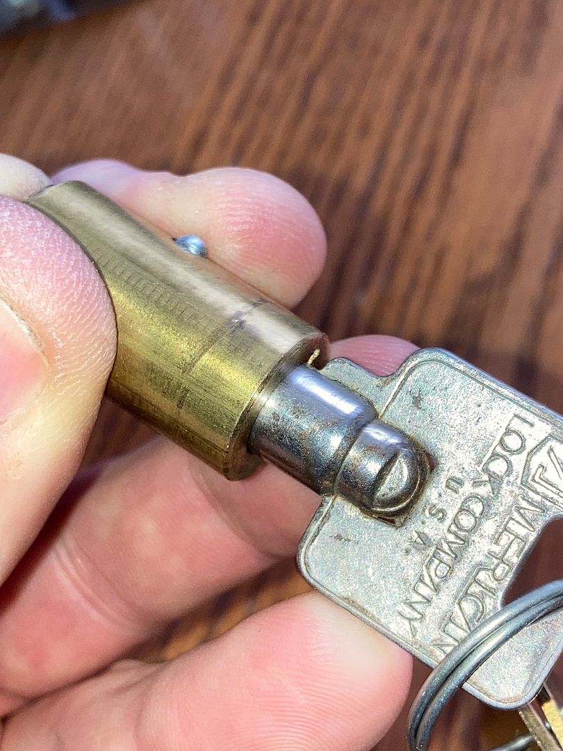
Yep! The key works. Remove the key, and place the stop spacer onto the back of the core.
Try to press it down with your thumb.
After that fails (
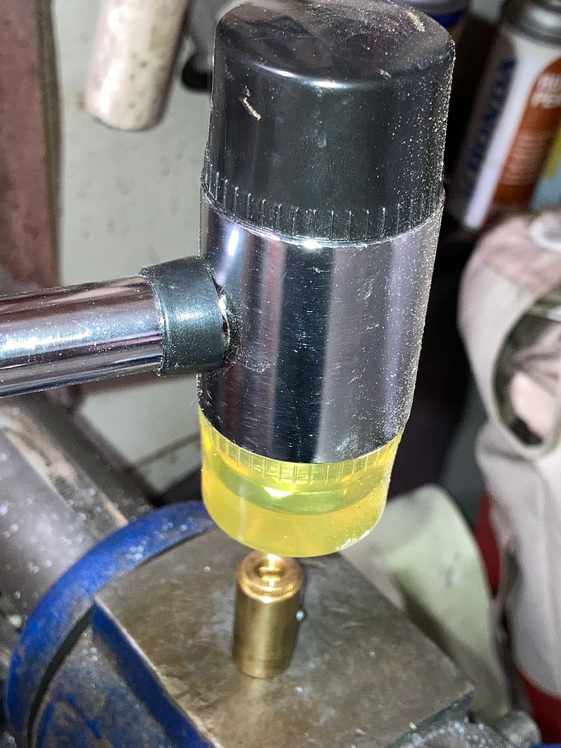
The stop spacer should be flush with the back of the core when it is set down.
Place the actuator on the back of the core, then install the core into the padlock body. Remember to have the steel pin in the left groove.
Install the trap door, sex nut, screw and you are done!
Hope this helps someone out. If not, just took up a lot of bandwidth for the pics!
Gordon