|
TOSL Project. A community project to "build a better mousetrap".
 by FarmerFreak » 18 Jan 2016 16:41 by FarmerFreak » 18 Jan 2016 16:41
supercat101 wrote:but for the most part fail to detach the tumblers from anything that can be manipulated prior to checking their positions.
Check this out. viewtopic.php?f=25&t=46768&start=15#p388942Same concept. Just using a second shear line that is locked in place until the inner core is rotated. I'm all ears if you can find a way to do it in a smaller format, that can't be easily forced over. The idea in the imgur picture above would work, but looks like it could be forced over fairly easily. Because the "sidebar" would have to be thinner than the pins, otherwise any master pins still in the bible during rotation will drop into the grooves for the sidebar causing the lock to jam up.
-
FarmerFreak
-
- Posts: 737
- Joined: 21 Apr 2009 11:58
- Location: SLC, Utah
by GWiens2001 » 18 Jan 2016 17:03
Was thinking of your MR modification while reading the first post, FF.  Gordon Just when you finally think you have learned it all, that is when you learn that you don't know anything yet.
-
GWiens2001
- Site Admin
-
- Posts: 7659
- Joined: 3 Sep 2012 16:24
- Location: Arizona, United States
by Joshua904 » 18 Jan 2016 17:56
Got it now. I misread and was thinking the bar had to disengage to let it turn.
Thanks!
-

Joshua904
-
- Posts: 134
- Joined: 5 Jan 2016 6:57
- Location: Jacksonville, FL
by supercat101 » 18 Jan 2016 18:38
That looks like my first imagined way of implementing the concept, except I had (and still do) no idea where to find a master-ring lock to play with. The way I would have interlocked things if the lock only had to turn one direction (as with e.g. a padlock) would have been to have pin 1 bitted to a level just *below* the warding, but have a small groove in the inner cylinder just to the side of the front-most chamber; the groove should be shallowly sloped toward the pin, and steeply sloped on the side opposite. Thus, to open the the frontmost pin would have to be at its lowest position when the operator started to turn the inner cylinder, whereupon it would drop into the groove and allow the outer cylinder to turn. Relative inner cylinder rotation would be blocked (transferring key rotation to the outer cylinder) once the pin reached the end of the groove. For purposes of binding order, I would make the pin in that chamber be a tiny bit fatter than all the others (so that unless it was in the groove in the plug, none of the other pins could bind), but tapered at the top (so it would have no trouble finding the hole in the upper cylinder).
-
supercat101
-
- Posts: 26
- Joined: 17 Jan 2016 14:02
by supercat101 » 18 Jan 2016 19:08
FarmerFreak wrote:I'm all ears if you can find a way to do it in a smaller format, that can't be easily forced over. The idea in the imgur picture above would work, but looks like it could be forced over fairly easily. Because the "sidebar" would have to be thinner than the pins, otherwise any master pins still in the bible during rotation will drop into the grooves for the sidebar causing the lock to jam up.
The imgur picture is close to what I had in mind, but I can think of three ways to improve torque resistance; I'm not sure how manufacturability on each would compare. 1. My original concept would be to have a spring push the rocker arm into the bible (opposite what's shown), but have an additional cammed groove which would push the rocker arm outward when the lock was at 12:00. That would avoid the need to have the cam push the rocker arm out of the blocking notch, and allow the ends of the rocker arm and plug to have a vertical or even reversed slope, so that no torque from the plug could transfer into the rocker. 2. Rather than having sloped surfaces at the ends of the cam notch, have tiny a leaf spring sit in a groove in the plug, and have the ends of the leaf spring serve as the sloped surfaces. If the slide bar let the top of the rocker push toward the bible, the bottom would ride up the springs and out of the groove. If it didn't, the bottom of the rocker would catch on the nastily-sloped sides of the groove, again preventing torque from transferring to the rocker. 3. If the lock only had to turn counter-clockwise (mirror things if only clockwise), make the rocker arm pivot so it can move to the left against a strong spring, and have a sloped barrier above and to the left of the bottom-left end of the rocker so that if top end of the rocker arm can push into the bible without difficulty, the bottom-left end will miss the barrier, but if the rocker arm can't move in that fashion pushing up on the lower-left end will cause it to move leftward and snag on the barrier. The first two approaches have the advantage that tension in the bible would be created via spring, reducing the possibility of "feeling" what's going on. The third would have the advantage of potentially minimizing the strength required for the rocker component. If the spot that fit the notch included a steel pin (with an axis running fore/aft) to catch on the barrier, the lock could be constructed so that forcing the lock by over-torquing would require shearing that pin. BTW, if the sensing bar had some free travel fore/aft, the design could be further extended by having a non-moving passive bar just below the sensing bar to hold pins in a consistent orientation, having "V"-shaped notches in the slide bar, and having some or all chambers loaded with a pair of half-pins. That would allow the sensor bar to move in and forward if it matched the notches in all the rear half-pins, or in and rearward if it matched all the front half-pins, but unlike most master-key systems it would be possible to have the lock accept e.g. 13542 or 12345 without accepting 12542, 12342, or any other combinations of the two bittings.
-
supercat101
-
- Posts: 26
- Joined: 17 Jan 2016 14:02
by supercat101 » 18 Jan 2016 19:45
FarmerFreak wrote:Because the "sidebar" would have to be thinner than the pins, otherwise any master pins still in the bible during rotation will drop into the grooves for the sidebar causing the lock to jam up.
One other point: at least as I envision it, the range of pin travel would be restricted so that the driver/sensing pins could never go completely above nor completely below the slide bar, so there should be no danger of wafers getting caught there. I would do that, among other things, so that if the driver pins were slightly spooled, only the top and bottom of the pin--whose shape was independent of the bitting--would touch anything inside the lock except when the slide-bar was engaged. If nothing that "knows" anything about the bitting comes in contact with anything else, there will be no way for someone manipulating the lock to sense it. I don't think that should be a particular problem with locks are designed to use the same length of driver pins for every possible bitting (quite common), since the chambers of such a lock must be tall enough to allow for a maximum-height key pushing on a maximum-length key pin and a driver which would be long enough for use with a minimum-length key pin.
-
supercat101
-
- Posts: 26
- Joined: 17 Jan 2016 14:02
by Jacob Morgan » 18 Jan 2016 21:26
Any new lock design that has some validity is a good thing, but to make a difference it needs to be easily manufactured. Taking the concept of the OP, the sketch below is one idea on how to take that concept and maybe make it easier to produce:  It takes a normal rim mortise cylinder and drills two new sets of holes and adds some semi-circular cut-outs in the plug (with a Woodruff milling cutter, etc.) It would then take two sets of new pins and the top pin would need to be a mushroom-looking pin with a reduced diameter area of a given size. The operation would be that if the proper key goes in then the top pin is set properly which allows the plug to turn then at about 10-20 degrees of rotation the "core block pin" would be pushed clear of the plug. It would only do that if the "sidebar pin" could be pushed to the left and it would only go to the left if the top pin was correctly positioned. When the lock is re-locked the spring behind the top pin would push the "sidebar pin" to the right a bit which would (along with gravity and the high cuts of the key being pulled out) push down the "core block pin." If a person picked it, one or more of the dummy master pins would be pushed up above the plug. The plug would rotate anyway, but the "sidebar pin" could not travel left with the top pin out of position and therefore the "core block pin" would not move out of the way and the plug would not continue to rotate. There would be a brass strip crimped over the holes drilled for the two new pins, or a set screw. Instead of the two new pins, one could use a number of ball bearings, that might actually work better but would be a pain to assemble. I think this is the same concept that the OP had--it is his originality and not mine--this is just a different embodiment of it (if I understand it correctly) that might be easier to produce.
-
Jacob Morgan
- Supporter

-
- Posts: 571
- Joined: 30 Dec 2015 21:31
- Location: KY (north west)
by supercat101 » 20 Jan 2016 9:53
Jacob Morgan wrote:Any new lock design that has some validity is a good thing, but to make a difference it needs to be easily manufactured. Taking the concept of the OP, the sketch below is one idea on how to take that concept and maybe make it easier to produce:
What do you see as pushing the slide-bar into the bible? The pin-interference concept would be good for blocking the mechanism if the slide bar can't go into the bible, but it's important that the slide bar be kept *out* of the bible whenever the pin stacks are accessible. Perhaps a second pin fitting a different cam surface on the plug?
-
supercat101
-
- Posts: 26
- Joined: 17 Jan 2016 14:02
by Jacob Morgan » 20 Jan 2016 13:13
I think that retracting the key and the resulting top pin spring pressure would move the top pins down and that would force the side pins to the right. Once they were to the right they would stay there until the plug was rotated. Maybe it would be too fiddly for real life, but that was the thought.
-
Jacob Morgan
- Supporter
-
- Posts: 571
- Joined: 30 Dec 2015 21:31
- Location: KY (north west)
by supercat101 » 20 Jan 2016 19:04
Jacob Morgan wrote:I think that retracting the key and the resulting top pin spring pressure would move the top pins down and that would force the side pins to the right. Once they were to the right they would stay there until the plug was rotated. Maybe it would be too fiddly for real life, but that was the thought.
The issue isn't pushing them right--the issue is pushing them left. If the cam-operated pin pushes out before the slider pin moves left, there will be a very strong tendency for the slider pin to bind rather than moving left. What do you think of the idea of having a slide-bar which travels fore/aft? Modifying an existing top-loadable Euro-cylinder lock would simply require milling a slot through the bible, milling some cammed surfaces on the plug, and loading suitable pins; in the simplest manifestation one would lose two pins, but if one were to start with an 8-bit lock and drill the last pin chamber of the plug below the level of the warding, putting a pin in there would block attempts at bypass, while having six useful pins left over. Otherwise, do you understand my idea for having two separate bittings controlled by having two half-width driver pins in each chamber? What do you think of that?
-
supercat101
-
- Posts: 26
- Joined: 17 Jan 2016 14:02
by Jacob Morgan » 20 Jan 2016 20:35
Supercat101,
The idea is that the bevel (or a radius) on the end of the cam operated pin would intersect with a corresponding bevel (or radius) on the end of the horizontal pin at first contact then continued upper motion would push the bevel (or a radius) on the left--but if that means overly demanding tolerances it may be a no-go.
I don't completely follow the concept in your last post, could you post a sketch of it? I like the sound of it, just can't visualize all of it.
-
Jacob Morgan
- Supporter
-
- Posts: 571
- Joined: 30 Dec 2015 21:31
- Location: KY (north west)
by Squelchtone » 20 Jan 2016 23:04
supercat101 wrote:What do you think of the idea of having a slide-bar which travels fore/aft?
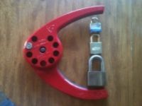
supercat101, I sent you a private message to clarify the use of the term "slide-bar" that you have been using, but I dont' think you saw my PM. I have unsent the private message and I'm going ask here. Are you meaning to say SIDE bar? A sidebar is a common mechanical part in high(er) security locks, a slide-bar seems like either a new thing in your invention, or perhaps you mean to say sidebar but think it is called a slide-bar. Here is an example of a sidebar in a Medeco lock:  please help me understand what you mean, thanks. Squelchtone
-

Squelchtone
- Site Admin
-
- Posts: 11341
- Joined: 11 May 2006 0:41
- Location: right behind you.
by supercat101 » 21 Jan 2016 9:30
Squelchtone wrote:supercat101 wrote:What do you think of the idea of having a slide-bar which travels fore/aft?
supercat101, I sent you a private message to clarify the use of the term "slide-bar" that you have been using, but I dont' think you saw my PM. I have unsent the private message and I'm going ask here. Are you meaning to say SIDE bar? A sidebar is a common mechanical part in high(er) security locks, a slide-bar seems like either a new thing in your invention, or perhaps you mean to say sidebar but think it is called a slide-bar.
The term "sidebar" typically refers to a device that sticks out of the plug to block its rotation. While the bar in my design may stick out of the side of the bible (it could also slide fore/aft) it would not directly block rotation as would be the case of sidebars in either Medeco or Abloy locks (or in knock-off disk detainer locks). I suppose "plate" might be better than "bar" for most of the design variations I can think of, but the key aspect is that it' fits into the bible rather than the plug, and will thus sense pins which cannot be manipulated while they are being sensed.
-
supercat101
-
- Posts: 26
- Joined: 17 Jan 2016 14:02
by Jacob Morgan » 21 Jan 2016 16:28
I think your concept is basically a lock inside a lock, where the first lock could be easily miss-picked, then that pin stack in the Bible would essentially be a new key to the second locking device and be hard to manipulate as plug rotation would prevent access to the top pins and there would be no resistance from the second lock on the pins until the plug rotated.
A clever idea but the devil is in the details, kwoswalt99's sketch would do it with levers but it looks like it would require precise parts and fitting and if the levers are small in size then a brute force attack might work. The sketch I posted might be easier to build but would not be adaptable to smaller cylinders and might be prone to jamming as parts wear and such.
Can you please provide a sketch of your design--how the top pins unlatch the second lock?
-
Jacob Morgan
- Supporter
-
- Posts: 571
- Joined: 30 Dec 2015 21:31
- Location: KY (north west)
by supercat101 » 23 Jan 2016 11:58
Jacob Morgan wrote:I think your concept is basically a lock inside a lock, where the first lock could be easily miss-picked, then that pin stack in the Bible would essentially be a new key to the second locking device and be hard to manipulate as plug rotation would prevent access to the top pins and there would be no resistance from the second lock on the pins until the plug rotated.
That's basically it. As with the forever lock, the goal is to make the "real" locking mechanism effectively inaccessible from the outside, as with the Forever lock, but without the complicated operational protocol. A clever idea but the devil is in the details, kwoswalt99's sketch would do it with levers but it looks like it would require precise parts and fitting and if the levers are small in size then a brute force attack might work. The sketch I posted might be easier to build but would not be adaptable to smaller cylinders and might be prone to jamming as parts wear and such.
Can you please provide a sketch of your design--how the top pins unlatch the second lock?
With kwosalt's sketch, If the part that fits the driver-pin grooves has "U"-shaped cuts in the front it should be able to travel very deeply into the grooves, thus allowing a fair bit of travel and avoiding the need for a super-precise linkage. I certainly do have some mechanical ideas, but I'm not as good an artist as some other people here. On the other hand, I might be interested in trying some 3d design tools; do you have any recommendations for free or cheap tools that I could use to do some renderings? While it would be cool to see the principle used in a lock used for securing things, part of my interest is from the other end: how would one non-destructively enter such a lock in a practical amount of time. If a camming mechanism turned lock rotation directly into motion of the pin-sensing bar or plate, variations in the driver pins might facilitate a micrometer-attack [depending upon security objectives, that may not be a bad thing, if it would still take longer than destructive entry; having a door lock which is so good that an owner who locks his keys out has to smash open a window or have a locksmith drill a lock, rather than being able to have a locksmith eventually pick it, isn't necessarily an advantage] but I'm curious if anyone else can imagine other weaknesses I'm not seeing. Further, if a mechanism were added to defeat micrometer attacks (as is done with some safe locks) what would be the next plausible means of attack? I'm also curious what key-operated lock designs there have been (popular or not) which avoid ever having any direct mechanical linkage between validation mechanism and the outside world or anything supplied therefrom? Even the Forever Lock and the "dust-proof" lock shown in one of Schuyler Towne's videos have the key in contact with the validation mechanism, which would allow for the possibility of various kinds of impressioning attacks.
-
supercat101
-
- Posts: 26
- Joined: 17 Jan 2016 14:02
Return to The Open Source Lock
Who is online
Users browsing this forum: No registered users and 3 guests
|


