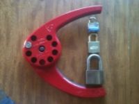
Raymond wrote:Due to lack of opportunity and experience I am not fluent in working with Corbin-Russwin large format removable cores. I was able to get a core out of a lock and measure the pins. The client states they do have a master key-change key set up but have no core key. The keyway is CO88. The core is the type with the center four pins turning the control sleeve. From the pin measurements below can someone deduce the most likely control key cuts? The change key was exactly the bottom pins only. I am not even sure which Corbin series to use with our code cutter.
Do you know the exact height of the control lug at the pin location? The plug is a standard .5”
Spaces (Bow to tip)
1 2 3 4 5 6
Wafers (inch)
.052 .133 .032 .131 .131 .017
Bottom pins
.205 .196 .236 .196 .237 .240
So your issue is that you only measured two pins in each chamber. In the control chambers there are 4 pins total and 3 pins in each non-control chamber. Second this was a system that was created by someone in the field, it is not factory.
Your keyway is 60 and it is 6-pin. CO88 = Z-60-6 (Z-class) (keyway 60) (6-pin)
The 3rd pin up in the control stack is the magical one, it in relationship to the stack below it determines the control cut. Build up pins can be 0 (same) bitting as below (0.163) or add (+) to or subtract (-) from the stack height below. The 4th pin in the control chambers is a master wafer corresponding to the valve of the control key in that position. The problem here is that the pin sizes you describe are not System 70 or Pre-System 70 even trying to factor in a bit of wear. Someone made this work with non-factory keys a non-factory pins.
Factory Rules for Conventional LFIC Cores:
1. The control key bitting must be identical to the TMK except in two positions.
2. The two positions which are different must fall within the range of positions 2 through 4, because those are control chambers.
3. Specifies that High Security ICs must use chambers 2 and 3 as the control chambers.
4. The two bittings which make the control key different must not be used in the progression of the system.
5. In System 70, do not use a #1 cut in the control positions of the control key. No build up pin is available to use a #6 cut to operate under it.
The above comes from Page 31 of the CR Keying Manual.
I think your best bet to determine the control key is to measure all the keys you can gain access to and knowing the rules find the two missing cuts in the two control chambers used in your system. If you have access to the master key and all of the change keys you will see a pattern of cuts that are missing from the system in 2 of the 4 control chamber positions. Those missing cuts are your control cuts in those chambers.
~~ Evan