


By Raymond
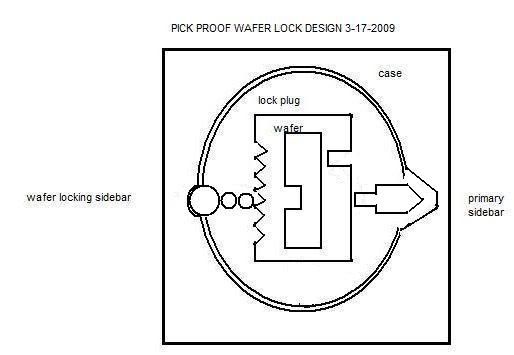
The above sketch will help explain the working concept of my pickproof wafer lock.
The round plug will be slotted for wafers to slide up and down. I recommend 6-10 wafers. Each wafer should be made of highly polished, hard, stainless steel to provide resistance to destructive entry attempts and extreme weather resistance. The wafers can be free floating and have no spring loading. Each must be free to move from side to side as moved by the key. Each wafer can be made of a length that it stops on the outer circumference of the plug and the wall of the case. The key will slide into a rectangular cutout in the wafer. The wafer will have a rectangular tab extending down into this key way slot. This tab will fit exactly into a groove milled into the key. The groove can be varied in location from one side of the key to the other to create differing combinations. The groove will be milled continuously along the length of the key to contact and move all wafers to the specific location required of each to align the sidebar “V†cutout of all wafers with the primary sidebar. The tip of the key will have a “V†or funnel shaped entry point to enable it to snag the tab of any wafer from what ever position the wafer has moved to. As the key is withdrawn all wafers will be scrambled and left in the same location as the exiting groove of the tip of the key.
The face of the plug must have hardened drill resistant rods to protect both sidebars.
On the left side of the example is a wafer-locking-sidebar. It consists of a rectangular piece of metal with a ‘V’ point on one end and flat on the other end. The flat end contacts a round roller that runs the full length of the plug. The wafer locking sidebar should have a small spring on each end that lightly keeps the sidebar away from the wafers. This will prevent any unnecessary friction on the wafer as the key is inserted or removed. The roller fits snuggly into a corresponding ‘V’ groove cut into the case of the lock. This wafer locking sidebar roller must be longer than the primary sidebar so it will not fall into and be captured by the primary sidebar groove. The ‘V’ point of the wafer-locking-sidebar contacts the wafers where there are similar ‘V’ cutouts in each wafer. Each cutout corresponds to a specific depth of the key bitting. Any rotational pressure will force the roller and wafer-locking-sidebar into the ‘V’ cut of all wafers at whatever location they may at, at that instant. The wafers will all be frozen in place and no longer able to move or otherwise be manipulated.
On the right side of the sketch is the primary sidebar. This sidebar is spring-loaded outward in locked position and prevents the plug from turning. When a wafer is raised to the correct position, a position designated by the key bitting to align the cutout ‘slot’ in the wafer with the primary sidebar rectangular rod, turning the plug will force the primary sidebar into the plug. The plug can now turn left or right to an unlocked or locked position.
The timing of the two sidebars moving is critically important. This concept is what creates the pick resistance. The primary sidebar must not move or be forced into the plug until after the wafer locking sidebar has already frozen movement of all of the wafers. Therefore the ‘V’ groove in the case of the wafer locking sidebar must be very tight with the roller bar with no accidental movement allowed. The ‘V’ groove in the case of the primary sidebar must be just wider to prevent sidebar contact or movement before the wafers are locked in place. This is what provides such a high degree of pick resistance. When each wafer is locked in place, there will be no feedback or clue what the opening combination or position of the wafers should be.
The groove of the key will hold the tab on each wafer in the correct position without the need of a spring. Wafers can be made in both a left and right form so the key can be milled on both sides. This will increase pick resistance and make key duplication much more restricted. This will also eliminate the maximum adjacent cut specification (MACS) reduction of possible combinations by creating the wafer thick gap between each cut. Planned placement of the wafers can also result in a true, reversible convenience key, as the combination will be the same on both sides. The key can be inserted either way.
If there are 6 wafers with a possibility of 5 bittings per space, the maximum number of theoretical combinations will be 15,625. With 8 wafers the number rises to 390,625. With 10 wafers the number rises to 9,765,625.
Master keying is possible by adding a second slot cut in any wafer.


