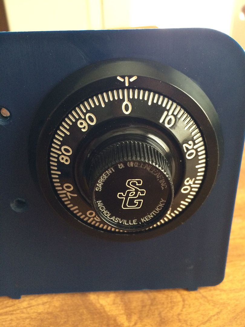
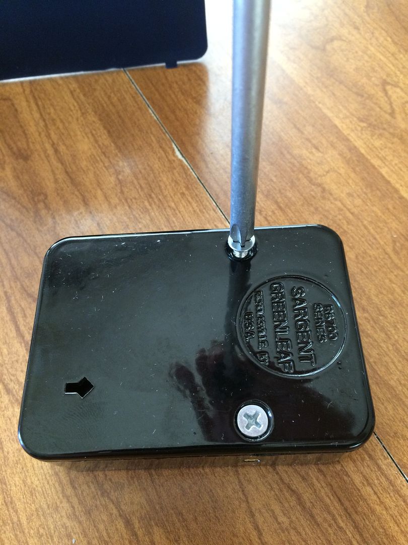
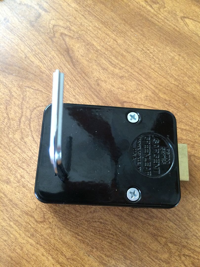
This pictorial is of a Sargent and Greenleaf 6730 safe lock. Some safe locks will be identical, or nearly so, while some others can be very different. However this is a very common lock.
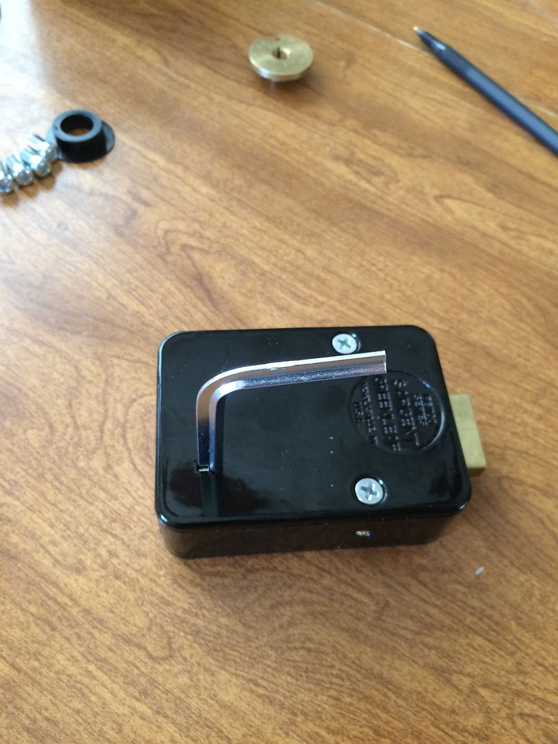
Mounted, it looks like this:
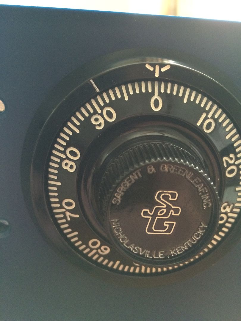
With the only exception being that they have a change index, which is 8 ½ numbers off. Here is a picture where I used a file to add the index mark at the correct location.
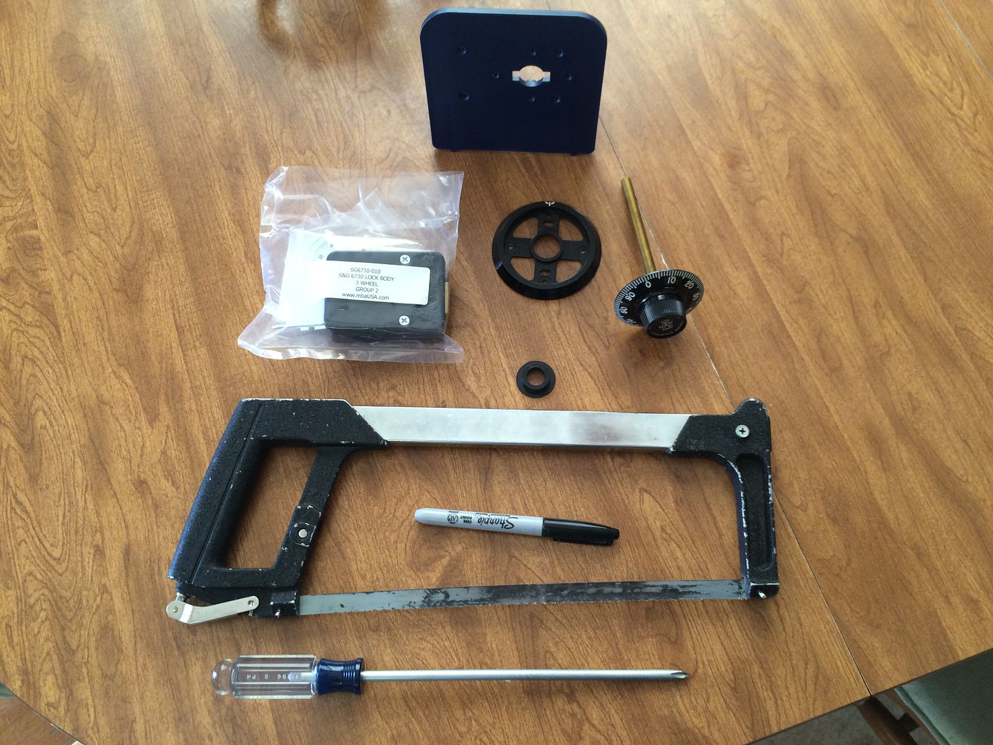
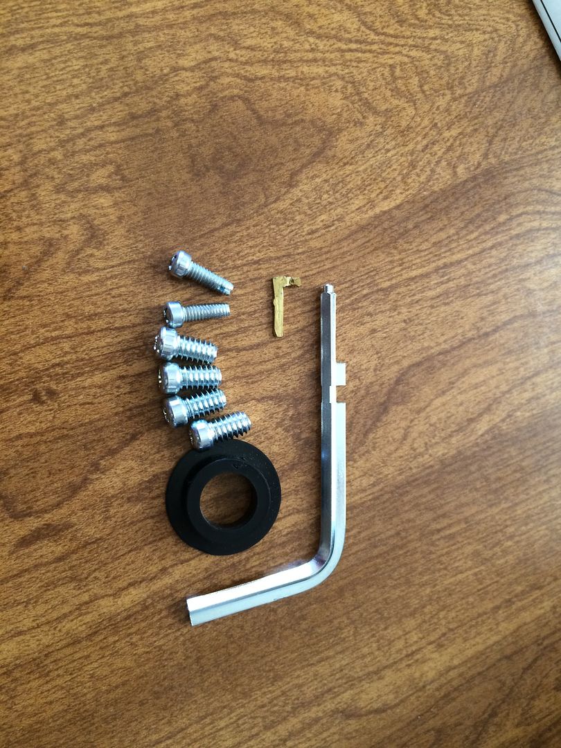
Here are the parts and the primary tools needed. The parts include the lock body, dial, dial ring, dial ring bushing, spline key and screws. The tools are screwdrivers, a fine point marker and a hacksaw. Also have a display mount.
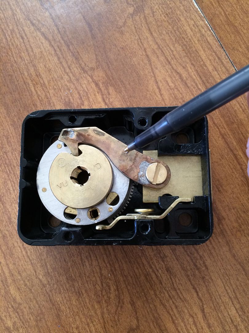
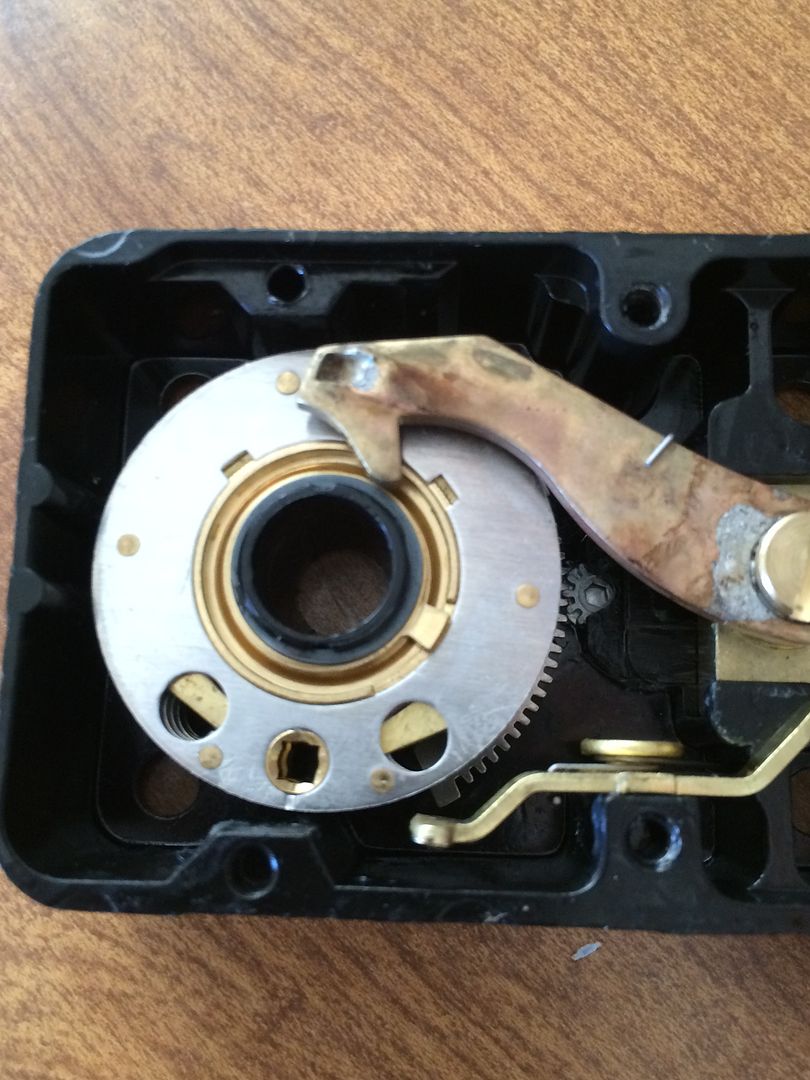
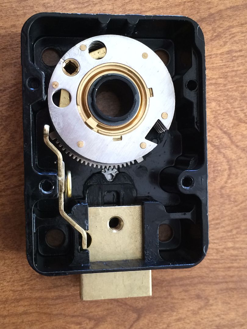
To start, take off the back cover of the lock by removing these screws.
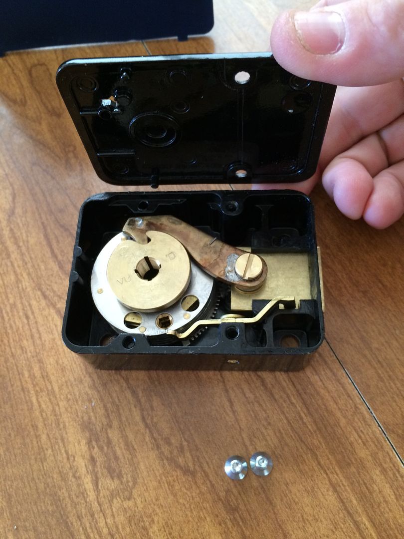
This is the bolt. This is what the lock uses to block the boltwork of the safe door.
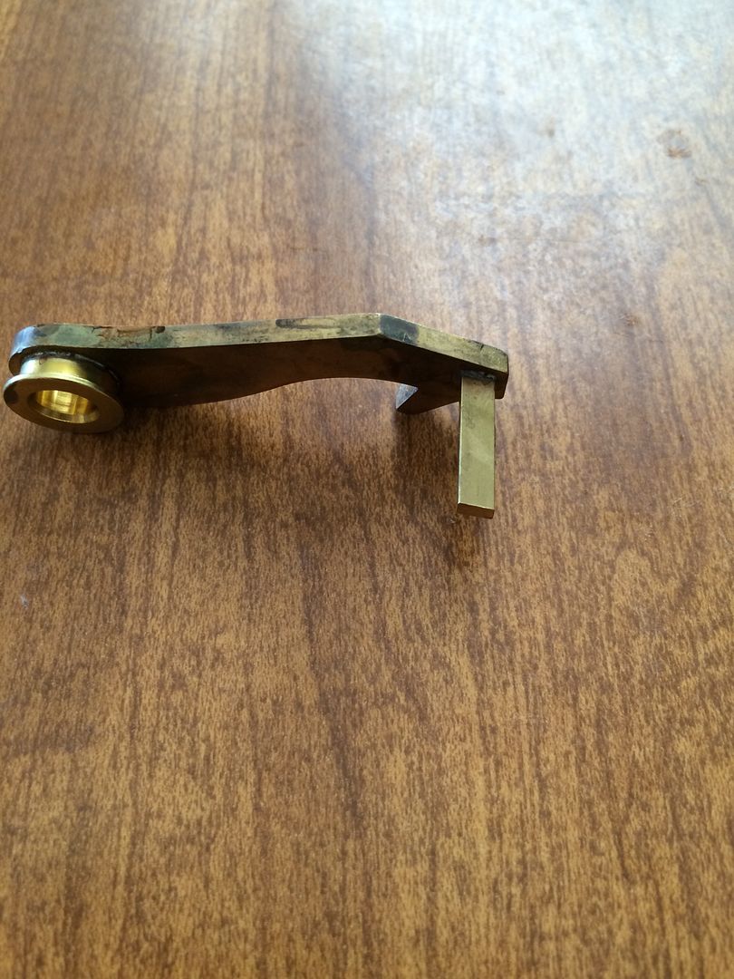
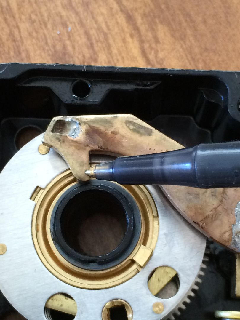
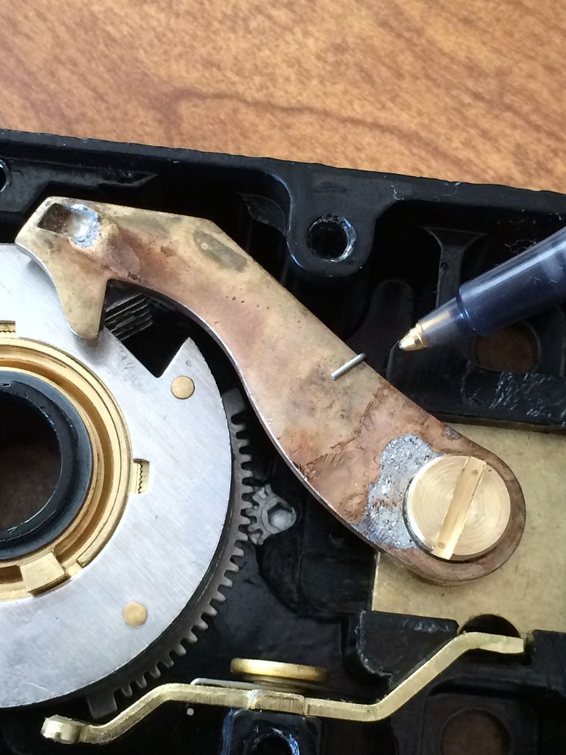
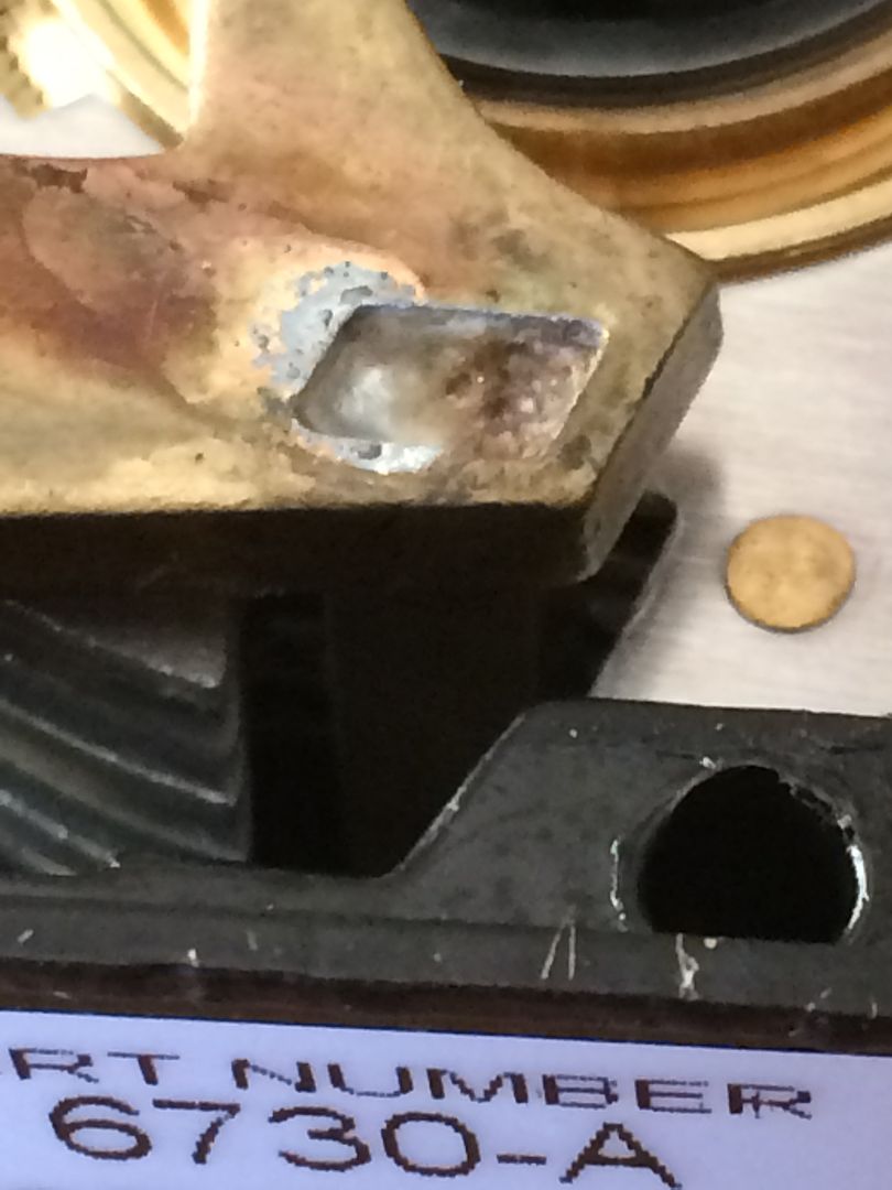
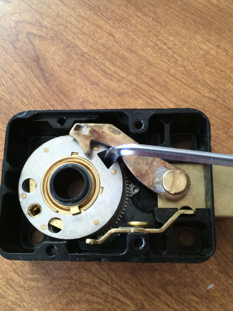
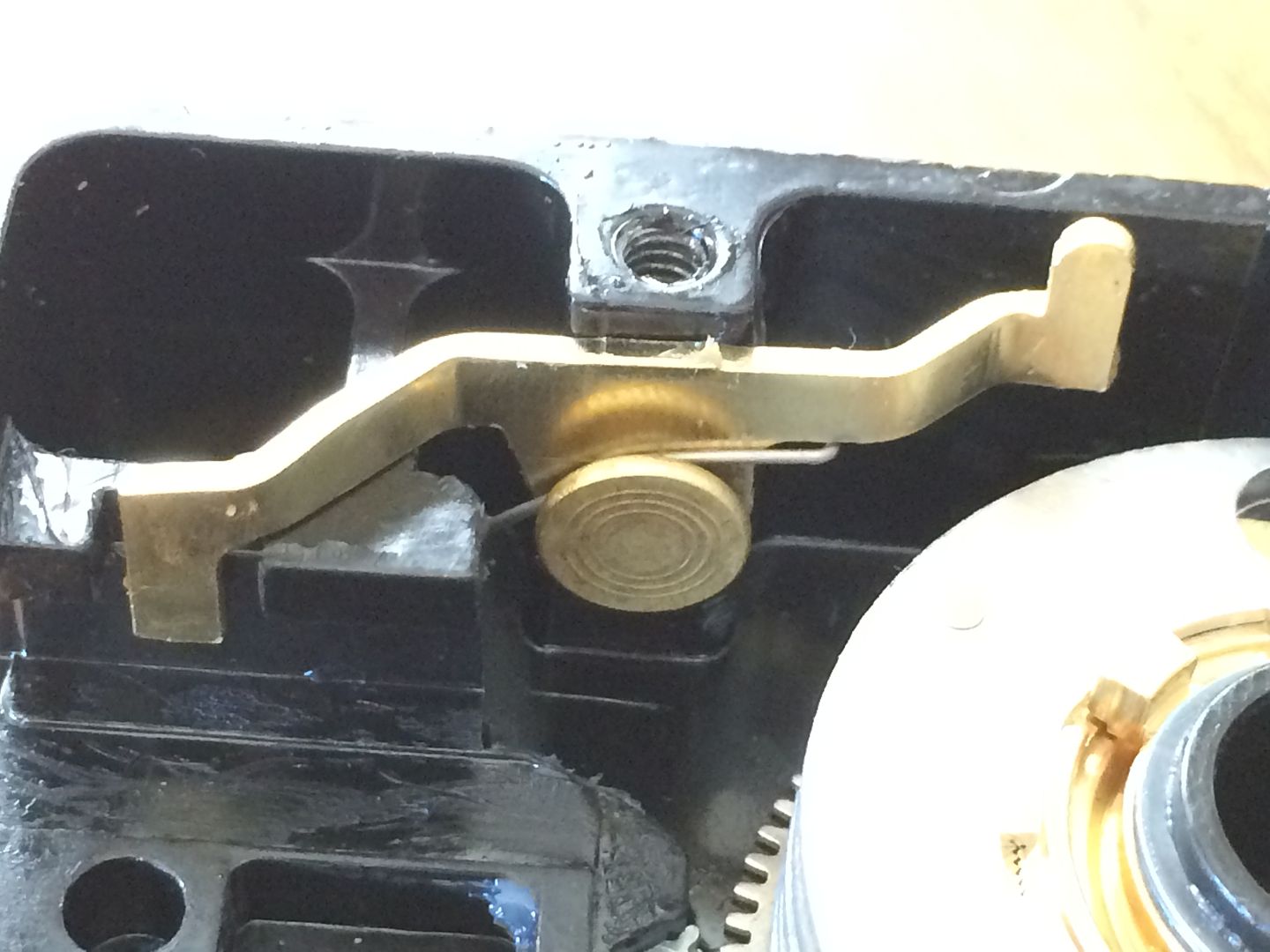
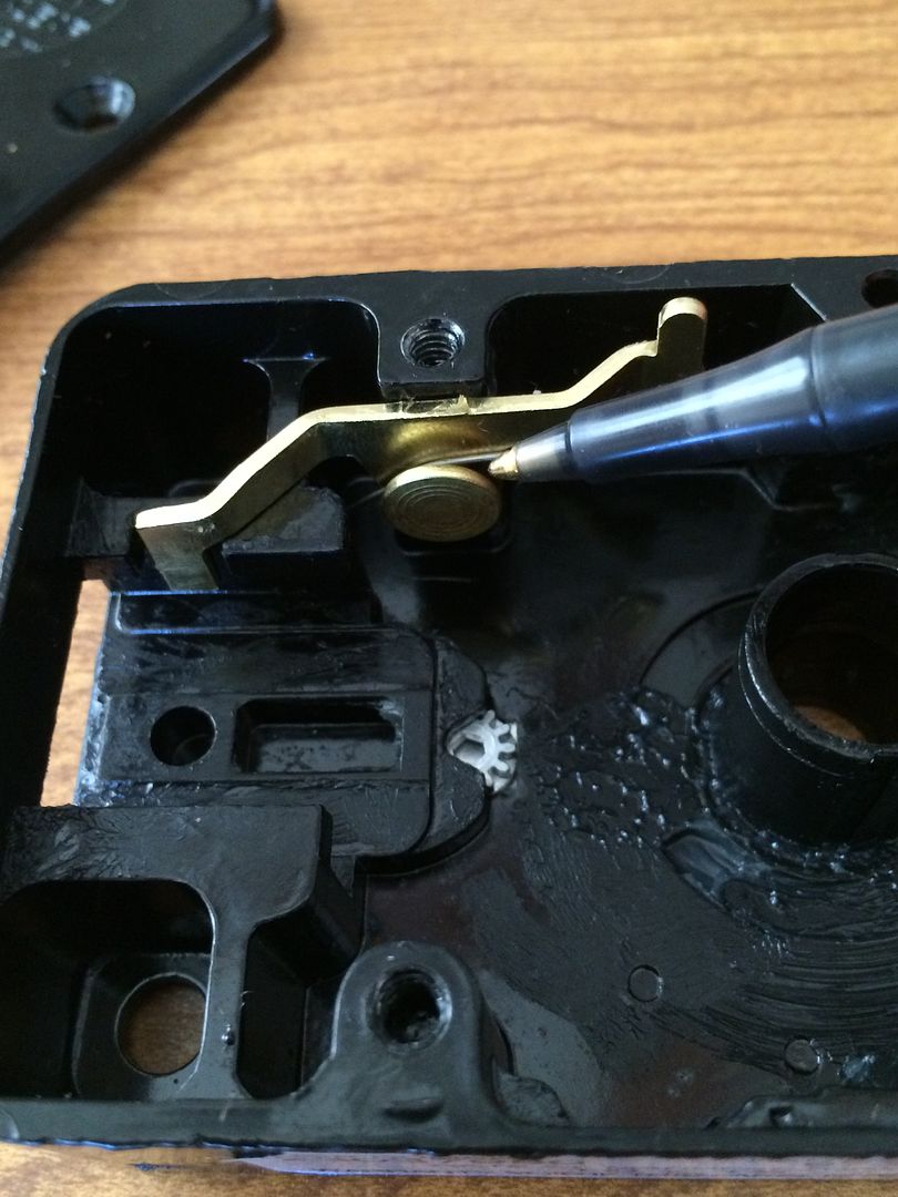
This is the lever.
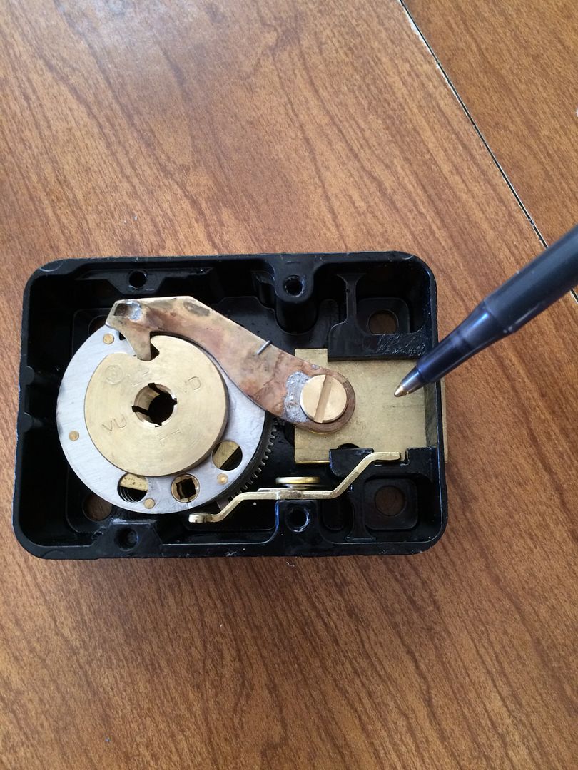
Here is the lever already removed in steps below, but showing another angle.
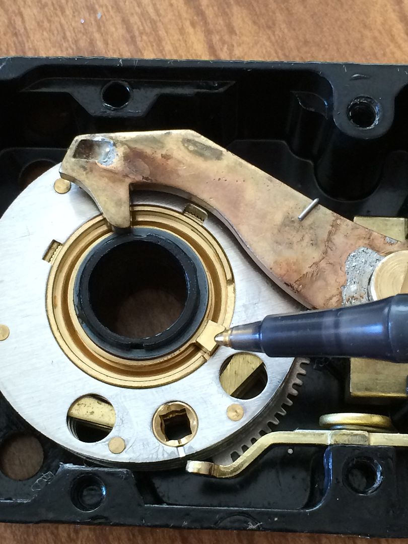
This is the fence.
This is the drive cam. This part can be lifted out if the dial spindle is not yet installed.
The bottom side of the drive cam has a post that engages the fly of the first wheel.
This is one of the wheels. (More about them later).
The drive cam has several parts to cover, Some we will deal with later. But here is the area where the nose of the lever drops in. The four grooves are possible locations for the spline key. More on this later.
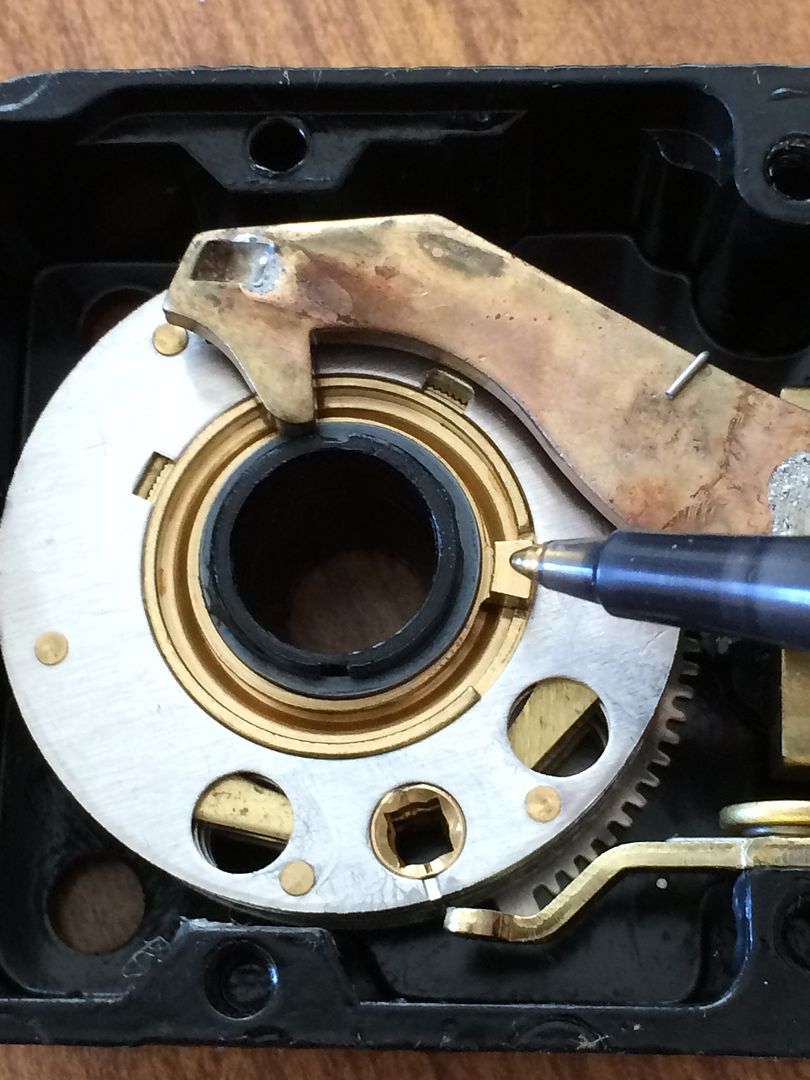
Right contact point. You don’t need to know what that means for now, just so you know what the term refers to.
Left contact point.
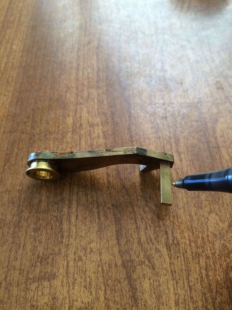
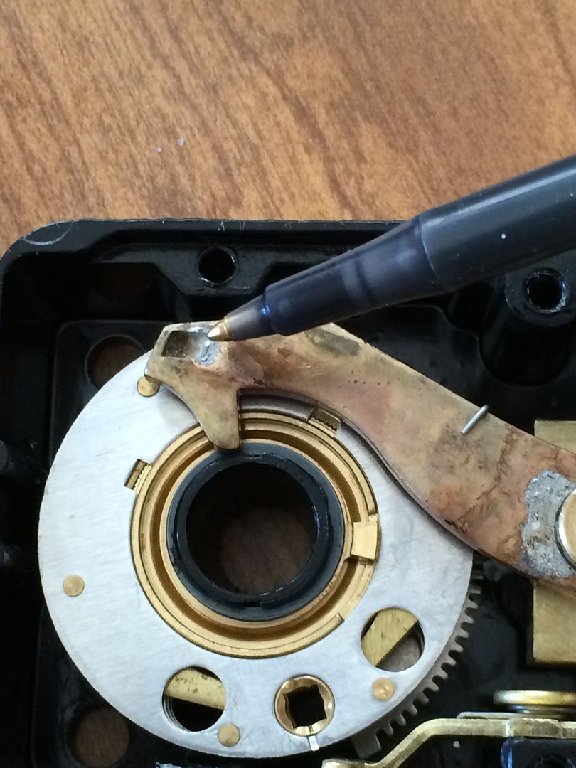
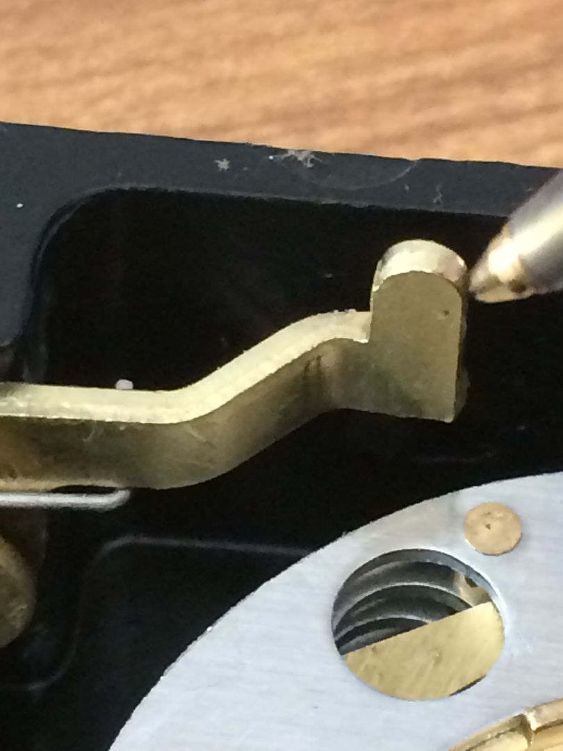
This is the nose of the lever, mentioned above.
The lever spring, which pushes the lever down towards the center of the wheels.
The change key hole in the wheel.

A fly. This is one of three in this lock. This is what allows the lock to be dialed in opposite directions, but still be able to open with the same combo when everything is working correctly. More on them later. But this fly is rotated to the limit in one direction.
And rotated in the other direction.
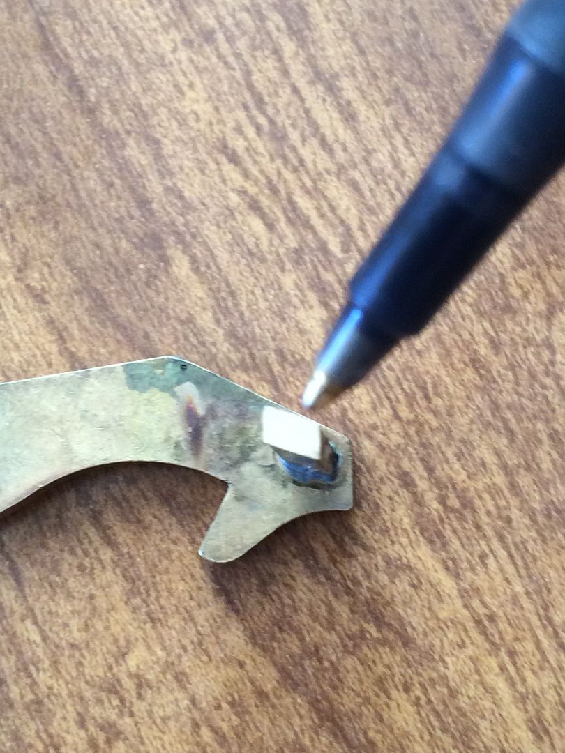
This is where the fence is mounted in the lever.
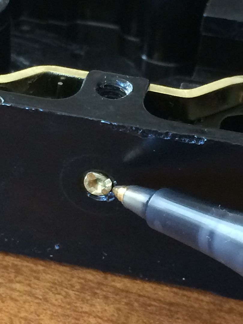
This is one end of a pivoting, spring loaded lever called the relocker. The back cover presses down on this end, and lifts the other end out of a hole in the bolt.
Here is the other end. Since the back cover is off, the relocker is engaging the bolt. Even if the correct combination is dialed, the bolt can not be drawn in.
Relocker engaged in the bolt…
And disengaged. Used my finger to act as the back cover on the other end, lifting the relocker out of the hole in the bolt.
This is the back cover end
Pressed down
Here the fence is down inside the gates.
This is one of the gates. Each wheel in the lock has one, and all must be lined up under the fence for the lock to allow the fence to drop and unlock the bolt. (Remember, the drive cam has already been lifted out).
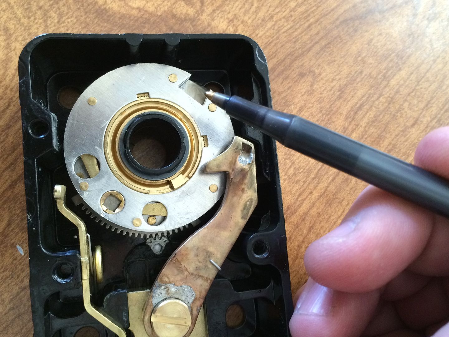
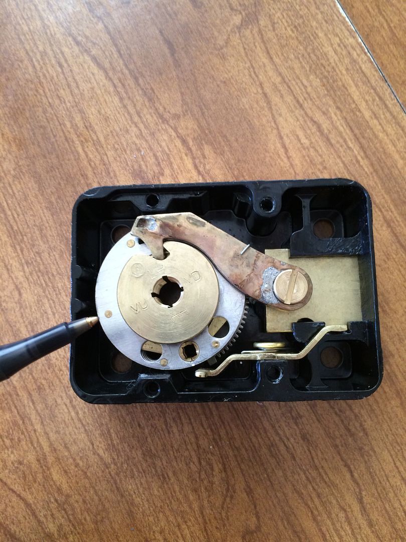
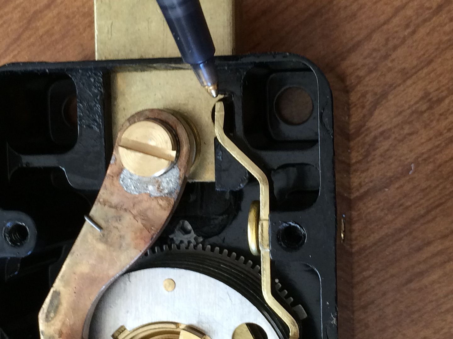
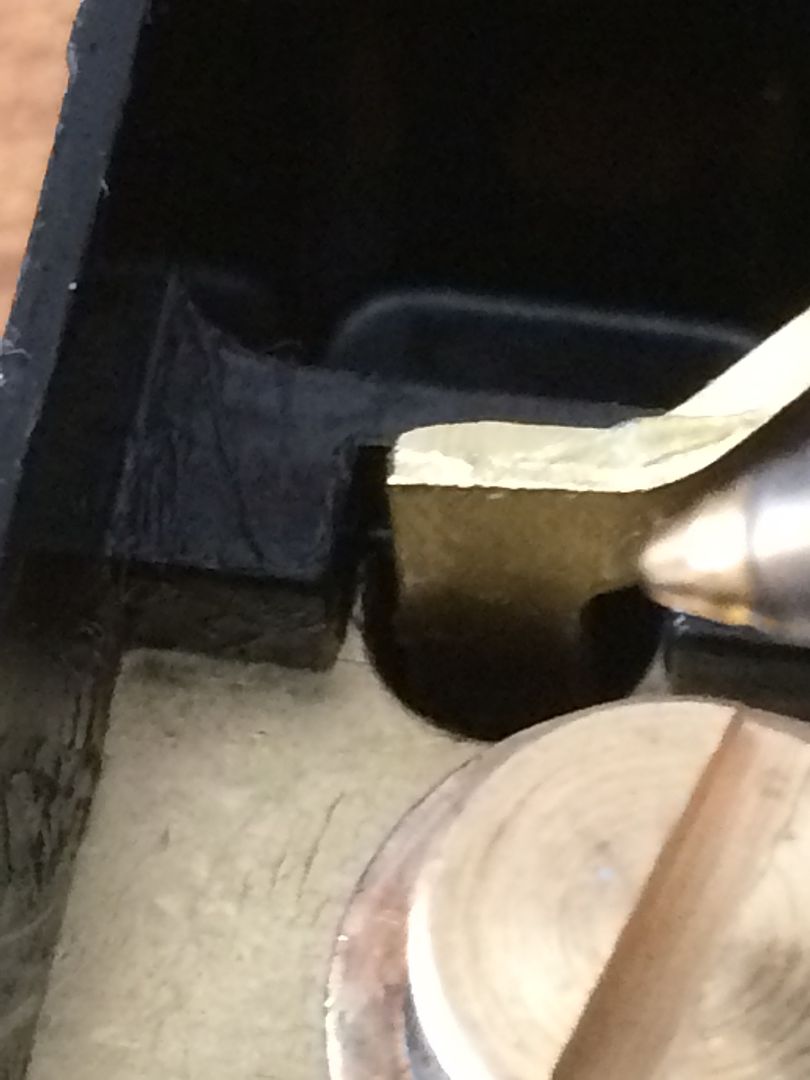
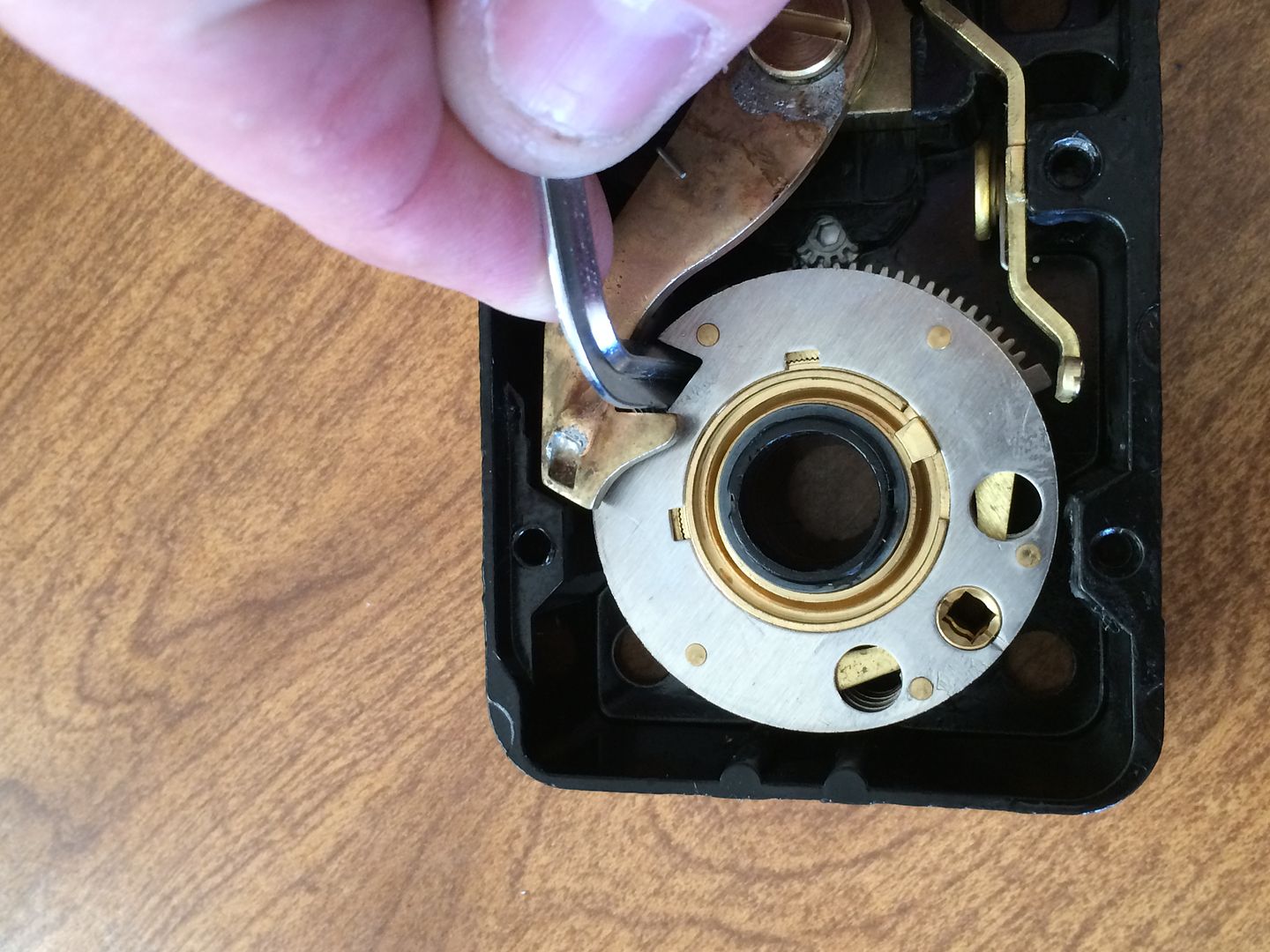
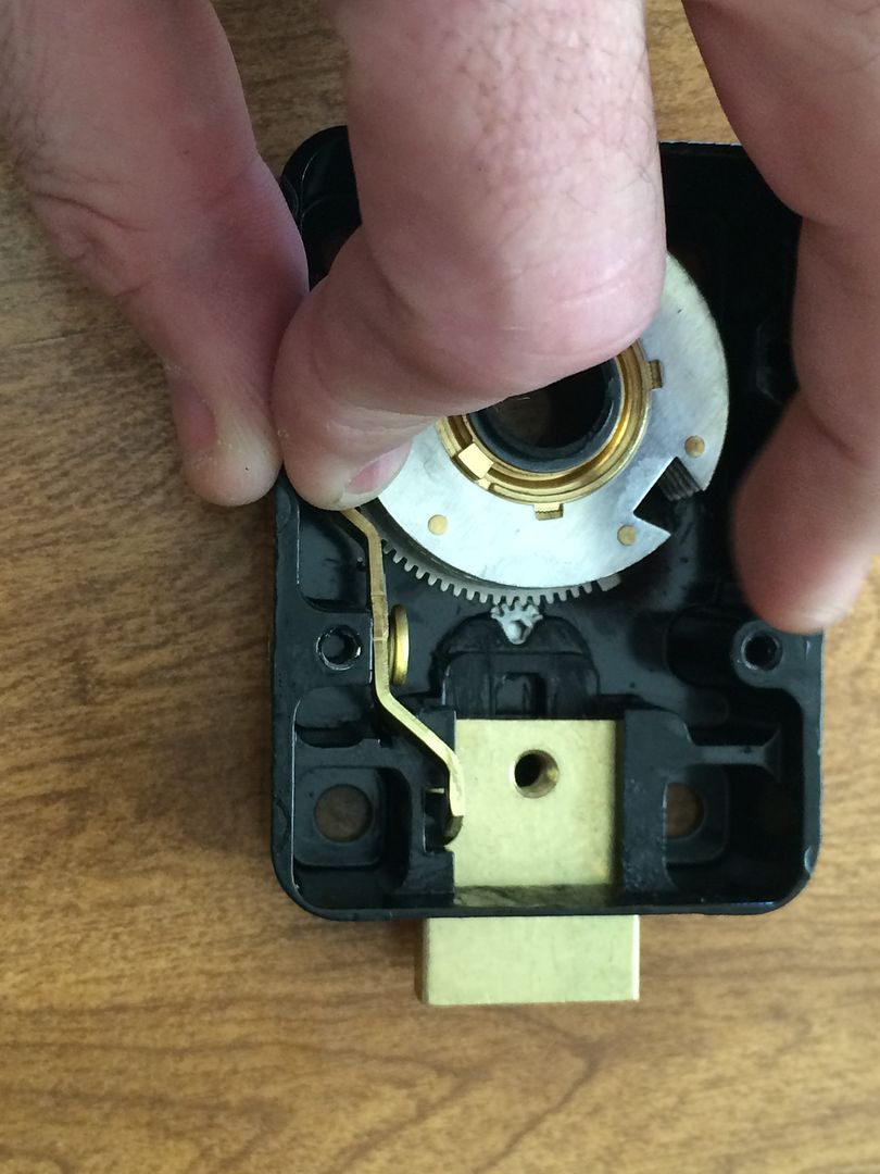
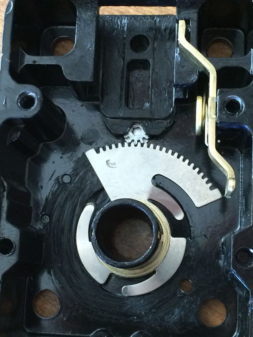
When the drive cam is installed, and the drop zone is not under the nose of the lever, the lever is held up like this. If you look at the lock body just above and to the left of the lever in this position, you can see that the lever can not be moved inwards, and since the bolt is attached to the lever, the lock can not be unlocked if the lever can not drop down.
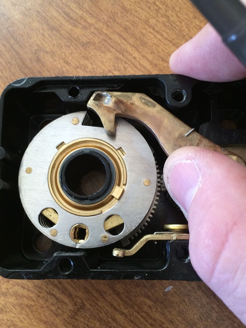
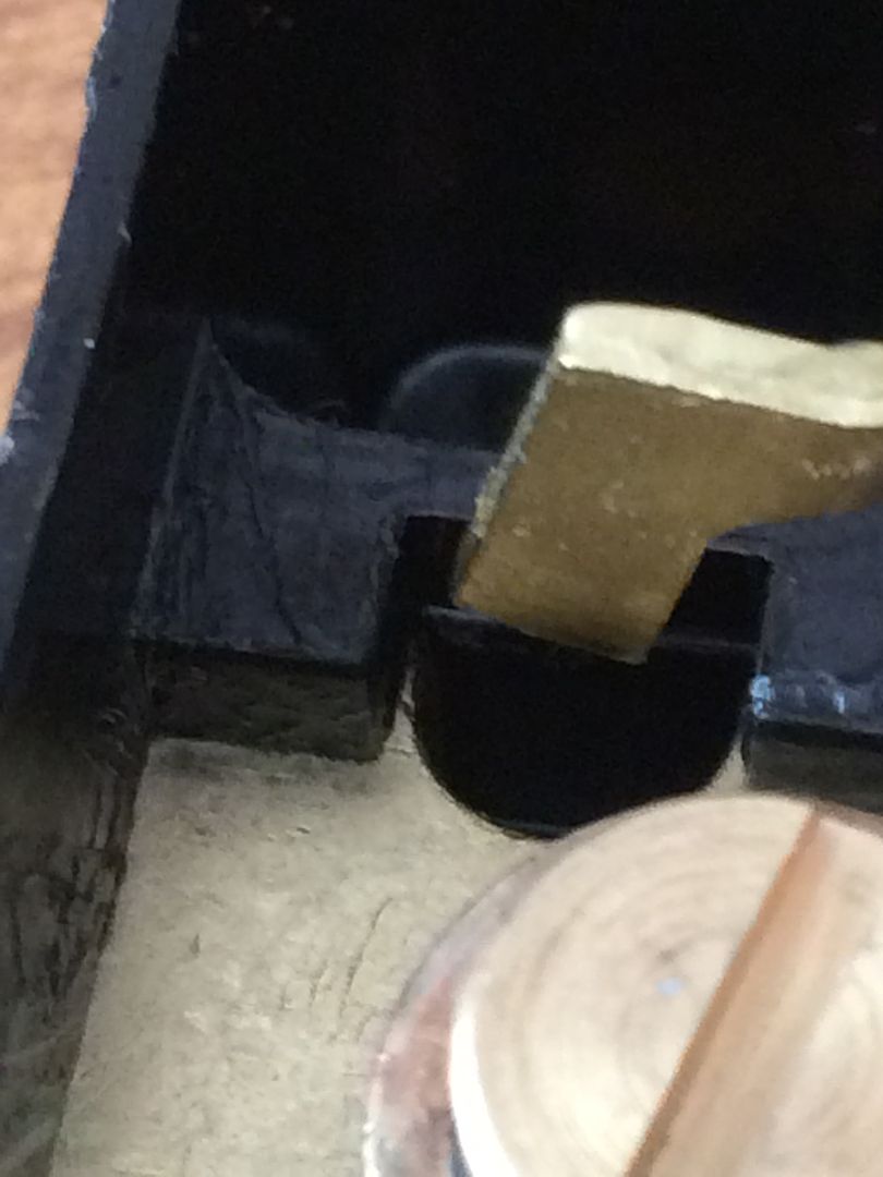
And when the gates are lined up and the drive cam (still removed in this picture) has the drop zone under the nose, the lever drops down like this, clearing that molded blocker in the lock body.
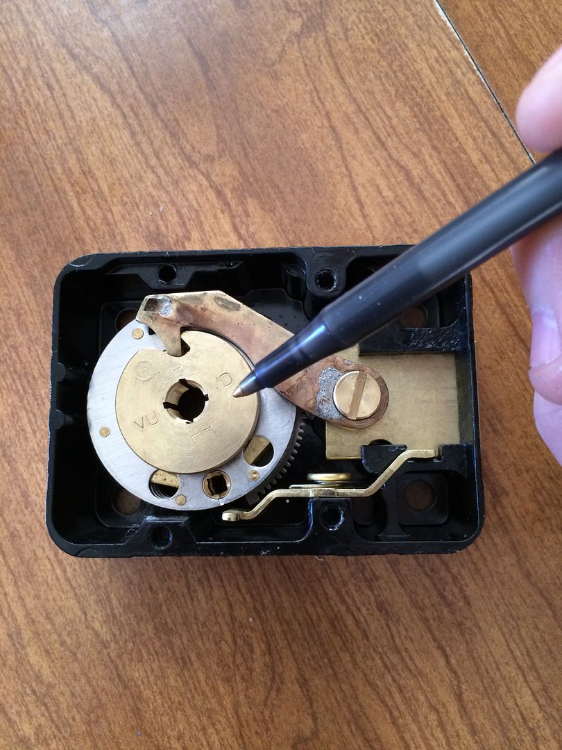
Two ways to line up the change key holes with the back cover if you don’t have the combo. One is to use a tool (in this case, the change key is used). Line up the gates, and use the tool to turn it until the nose of the lever stops it.
Put the back cover on, and look in the change key hole. Lined right up!
If the change key does not go all the way in, the wheels are not properly aligned. Here am holding the change key up just enough to pretend the deepest wheel is not lined up.
It should go all the way down, so the flag is entirely below the back cover.
That would allow the key to be turned. This is the ‘locked’ position of the change key.
And unlocked.
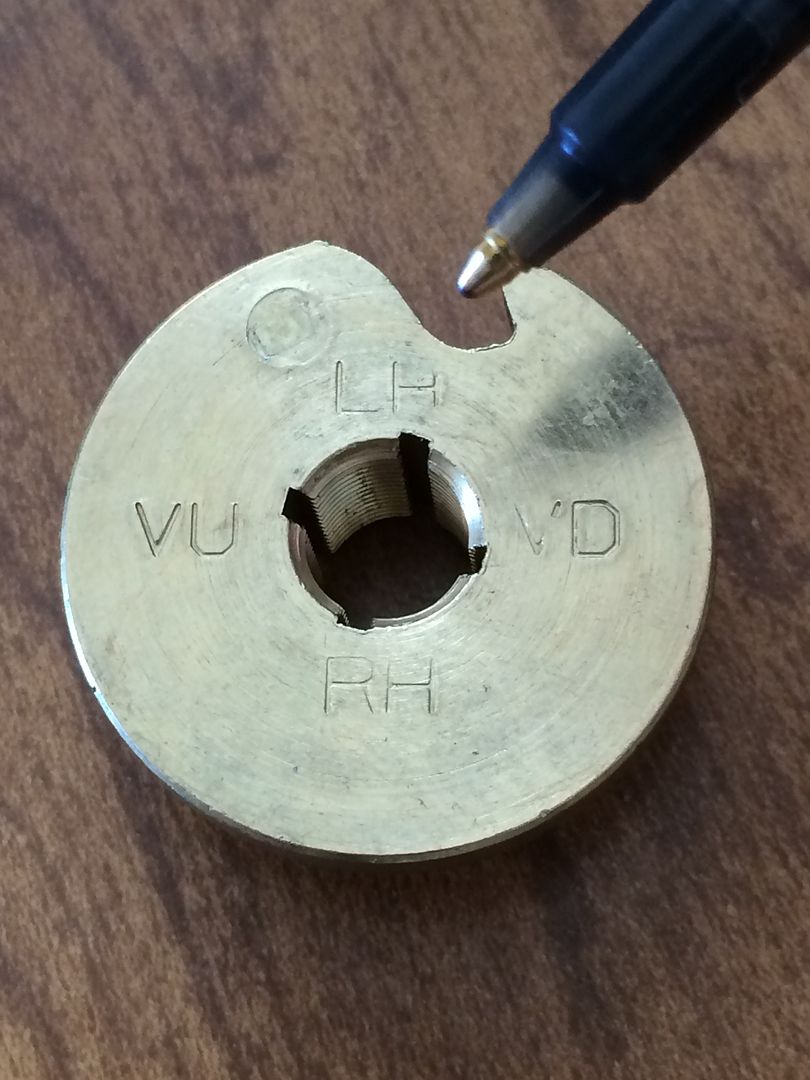
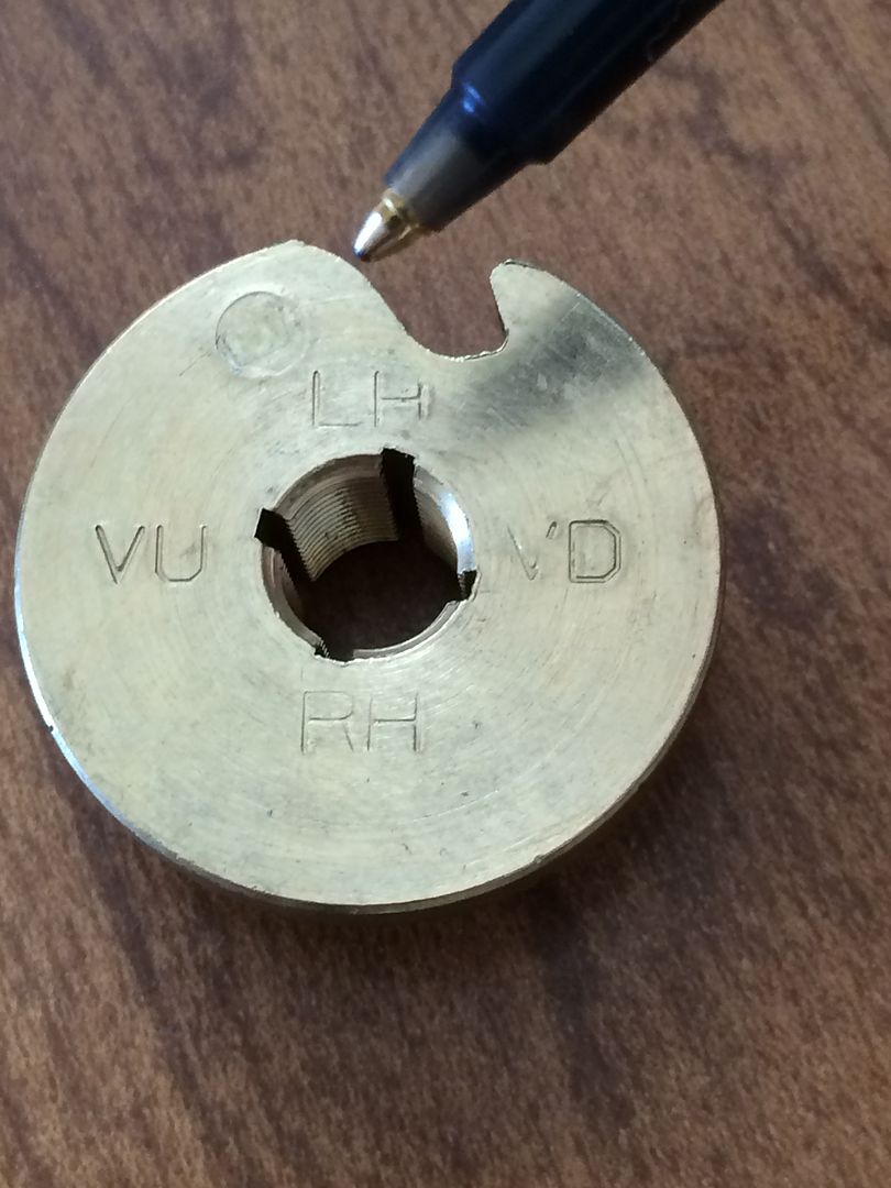
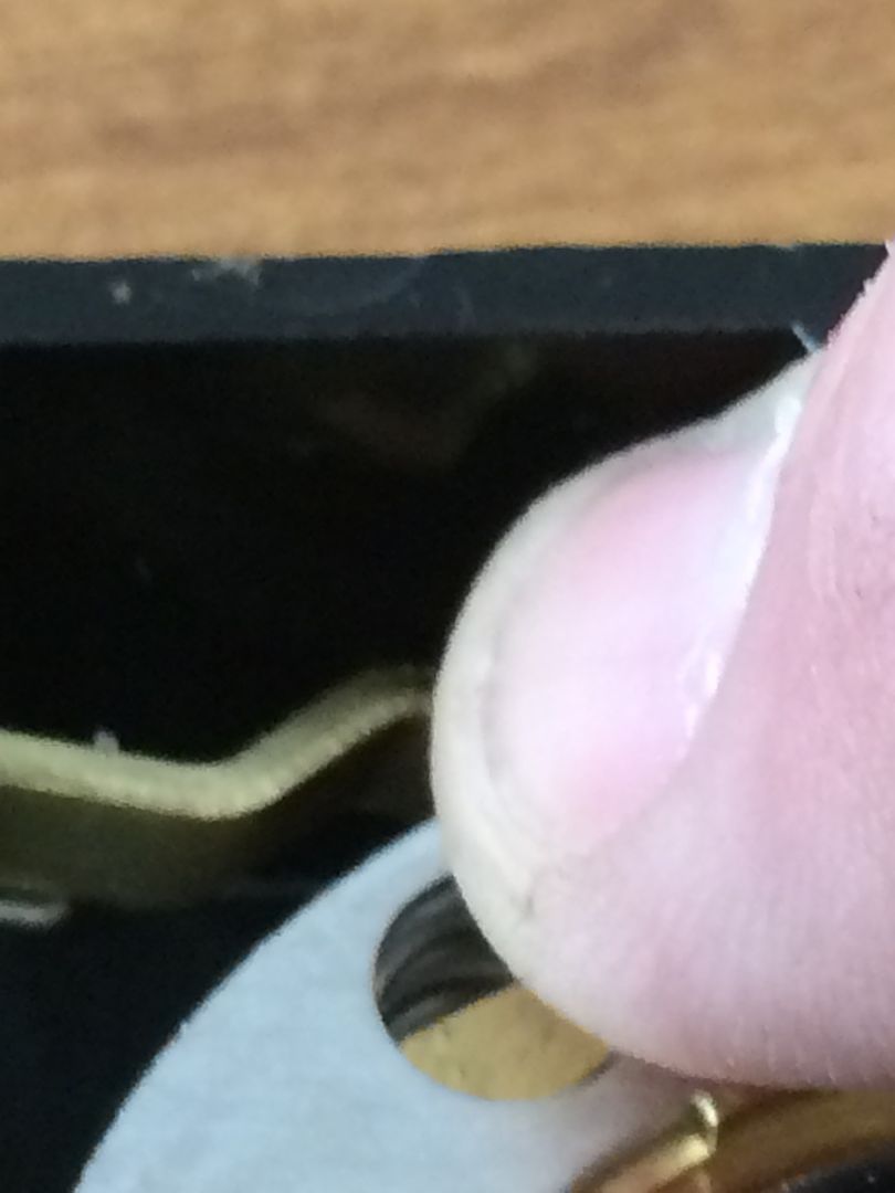
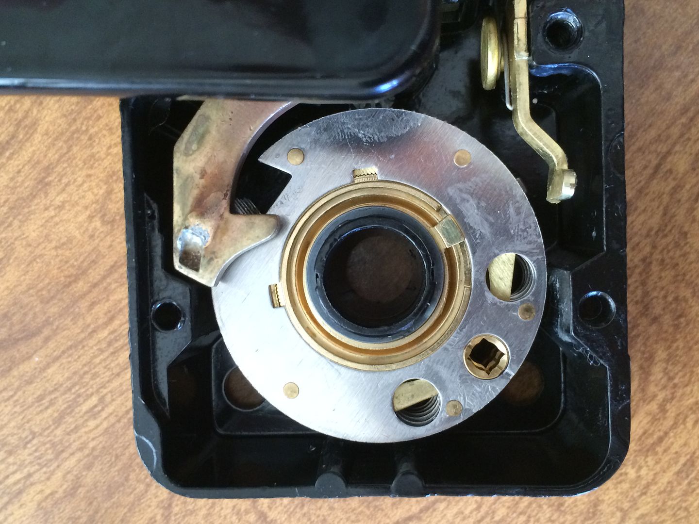
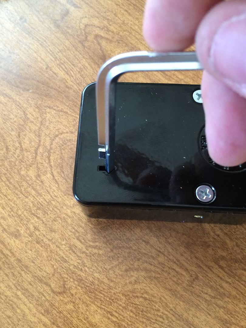
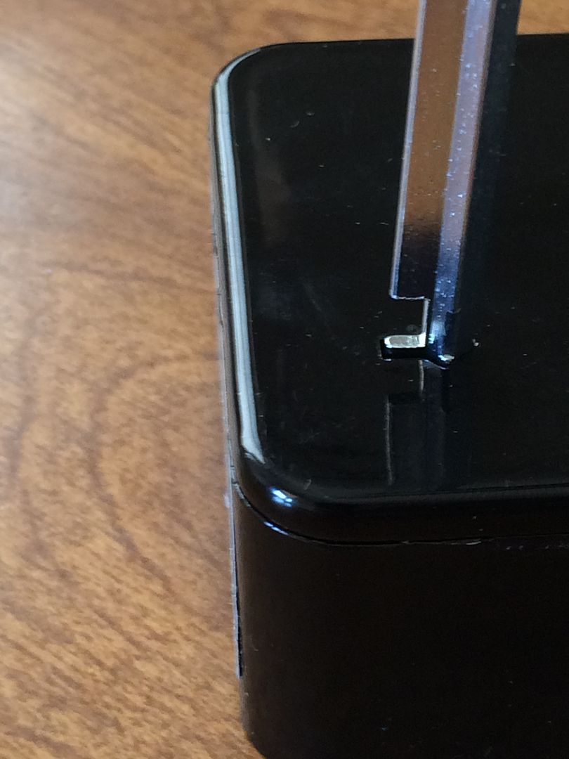
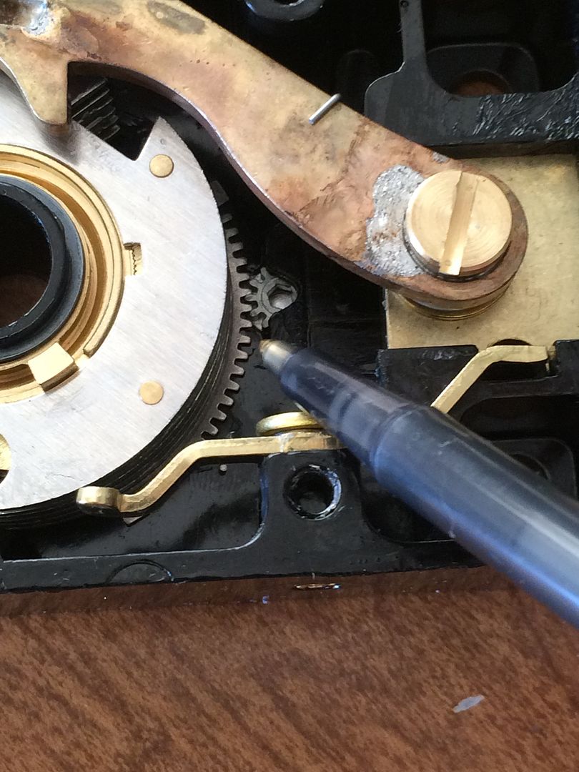
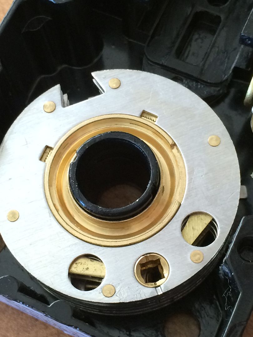
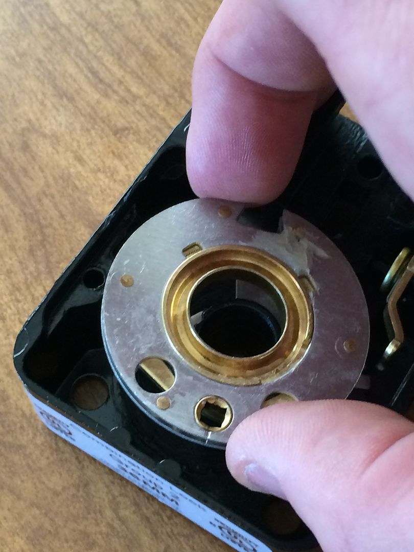
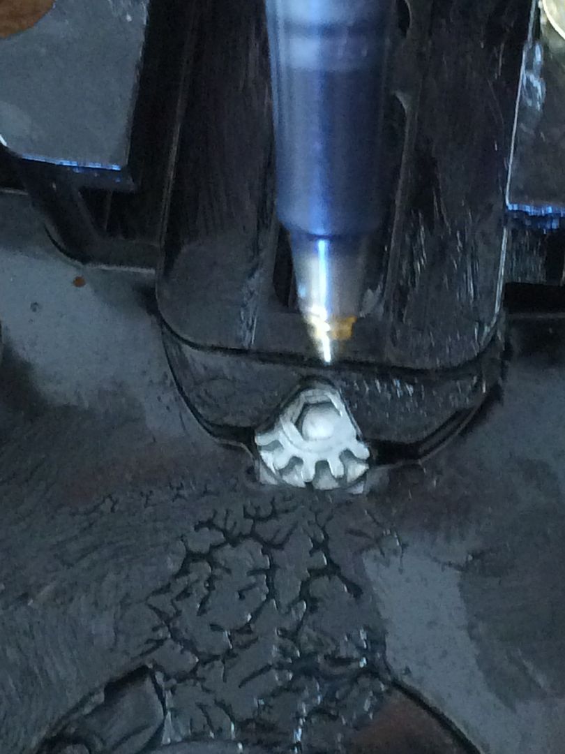
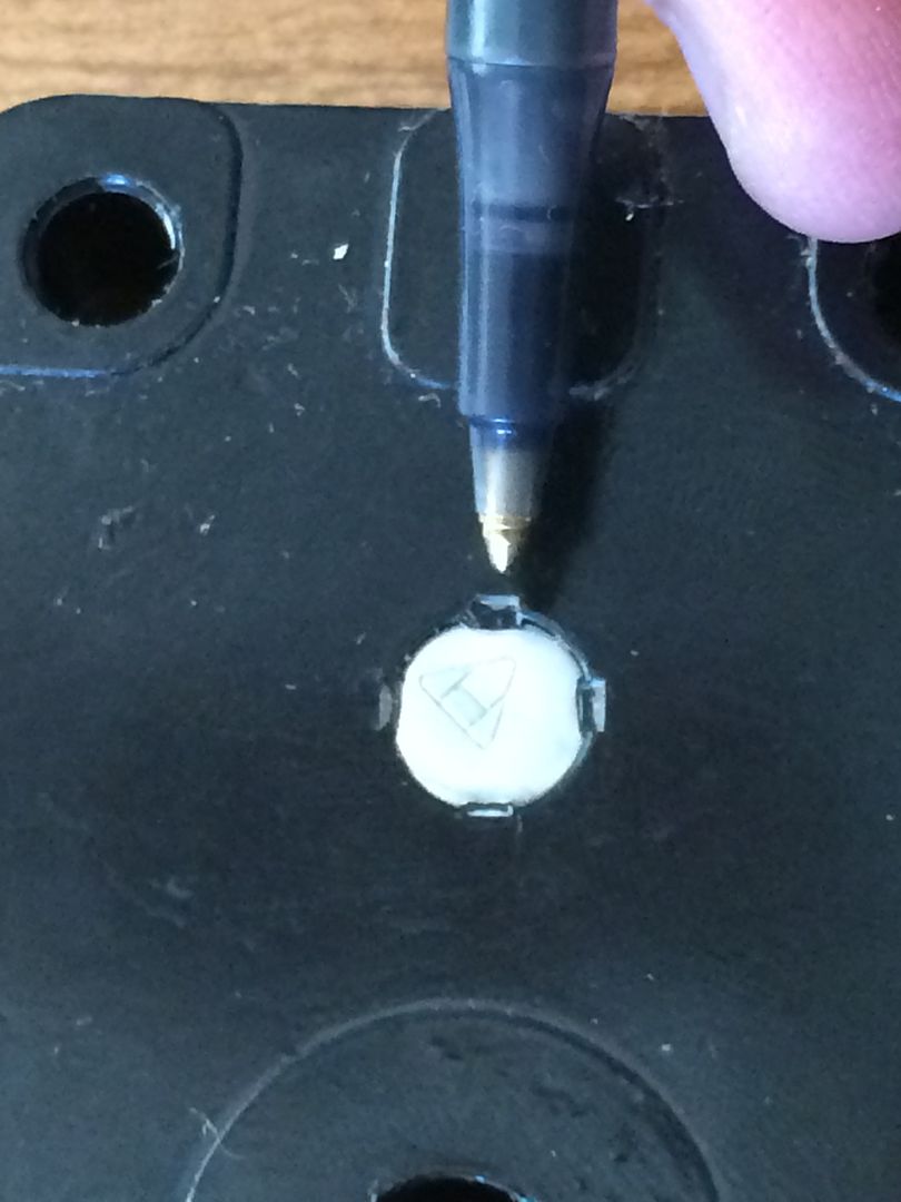
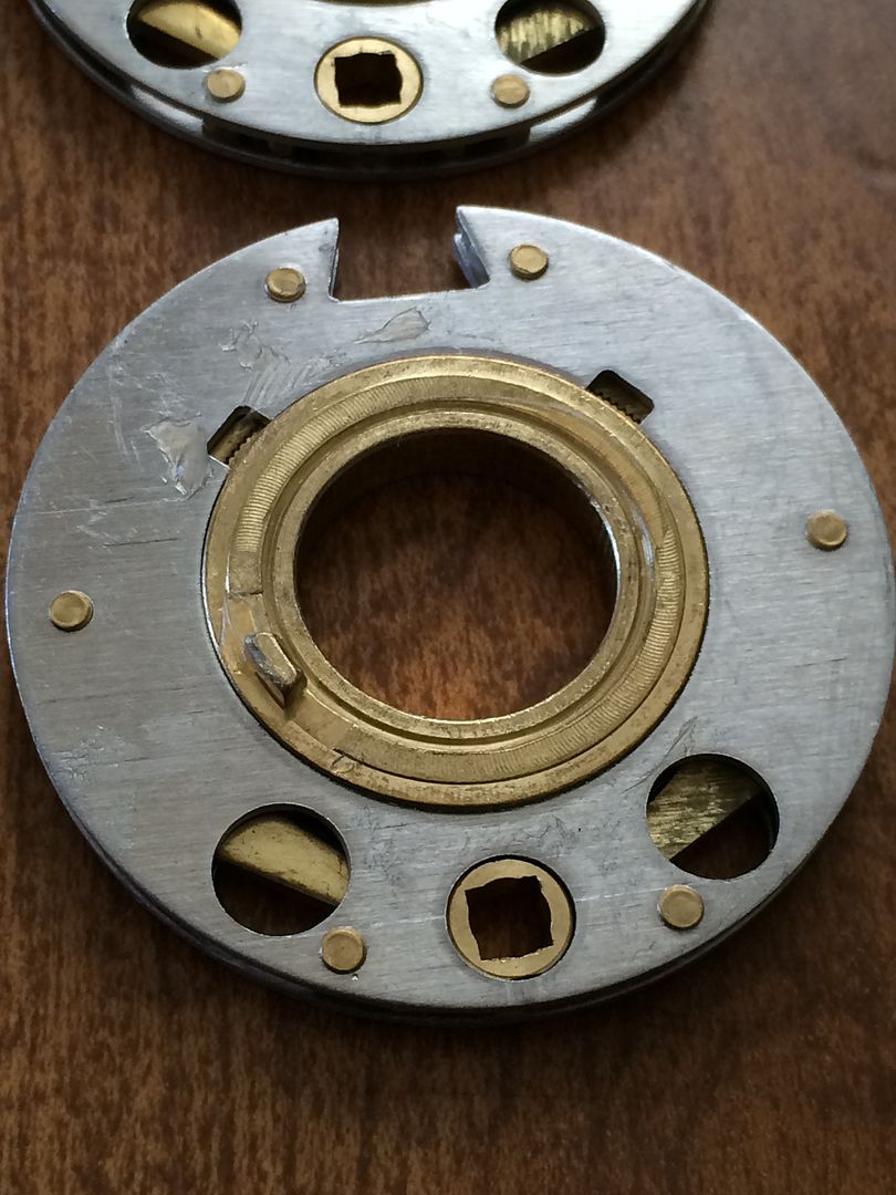
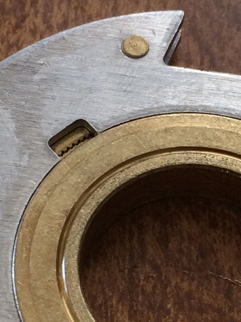
The other way is to line up the indexes in the change key holes in the wheels with the screw holding the lock body onto the safe. You can see the index on opposite sides of the change key hole. This is something that it is important to check. When the wheel is locked (Ready for normal usage of the lock), the index should be like this:
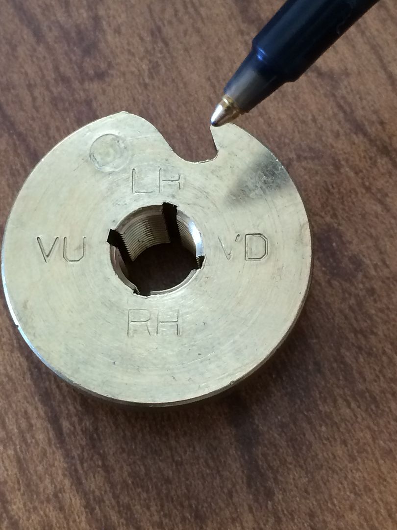
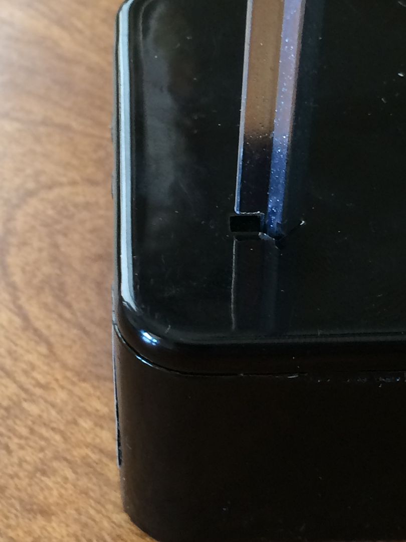
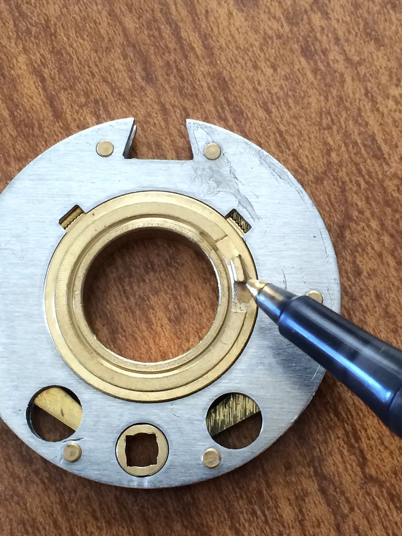
When the wheel is unlocked (ready for the combination to be changed), the index will be aligned parallel to the outer edge of the wheel.
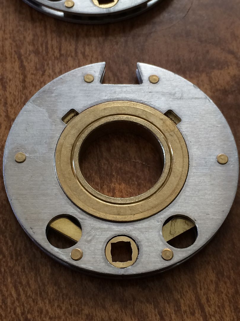
A somewhat common problem is when one or more of those change indexes are out of phase with the others. Perhaps two are locked and one is unlocked. A symptom of that would be the lock not functioning, and the combination seems to change itself. So be sure to check that all of them are aligned like this before using the lock…
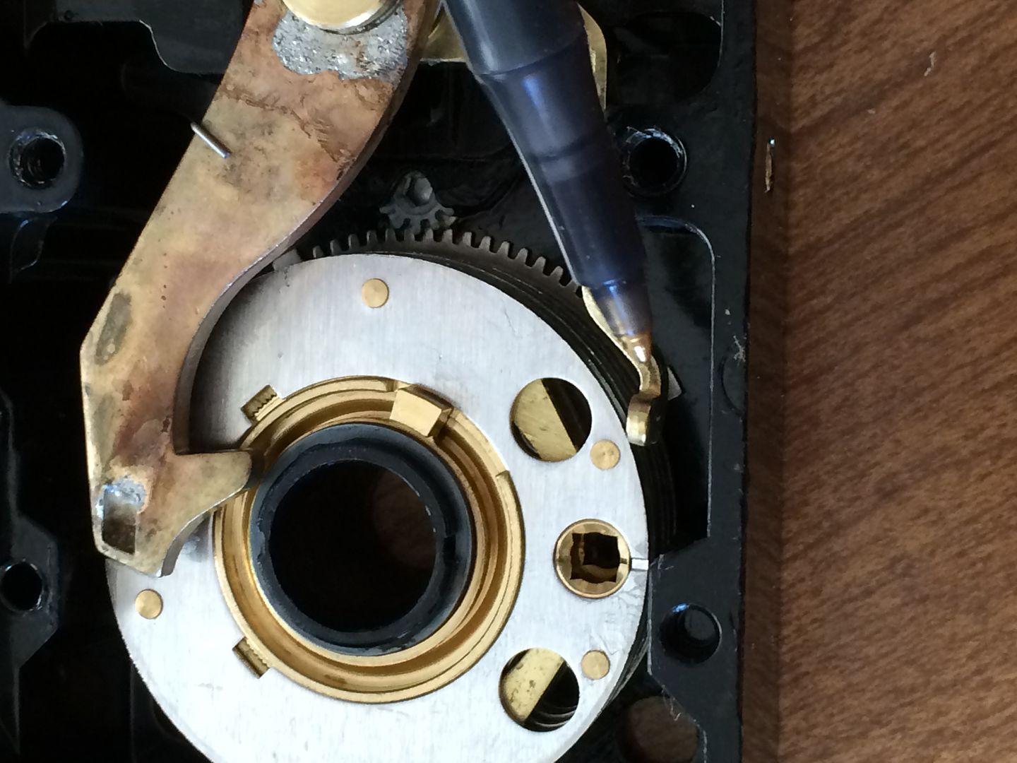
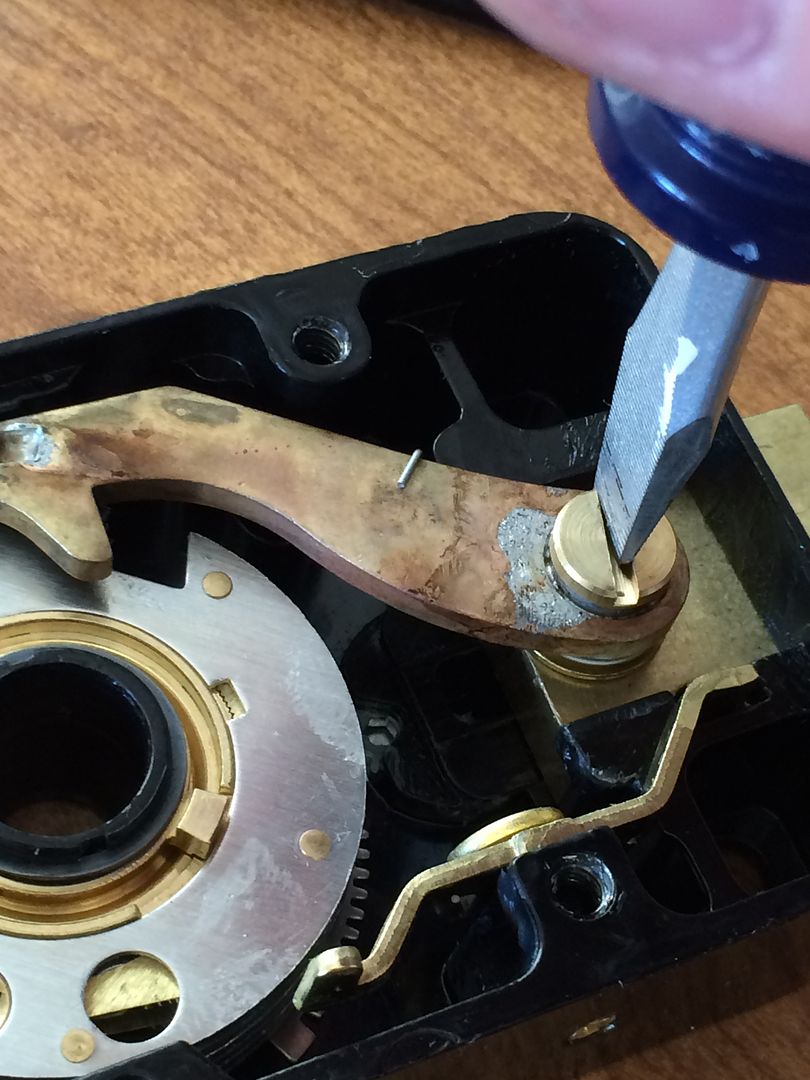
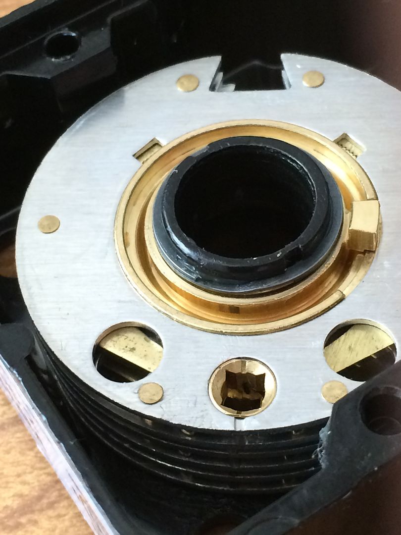
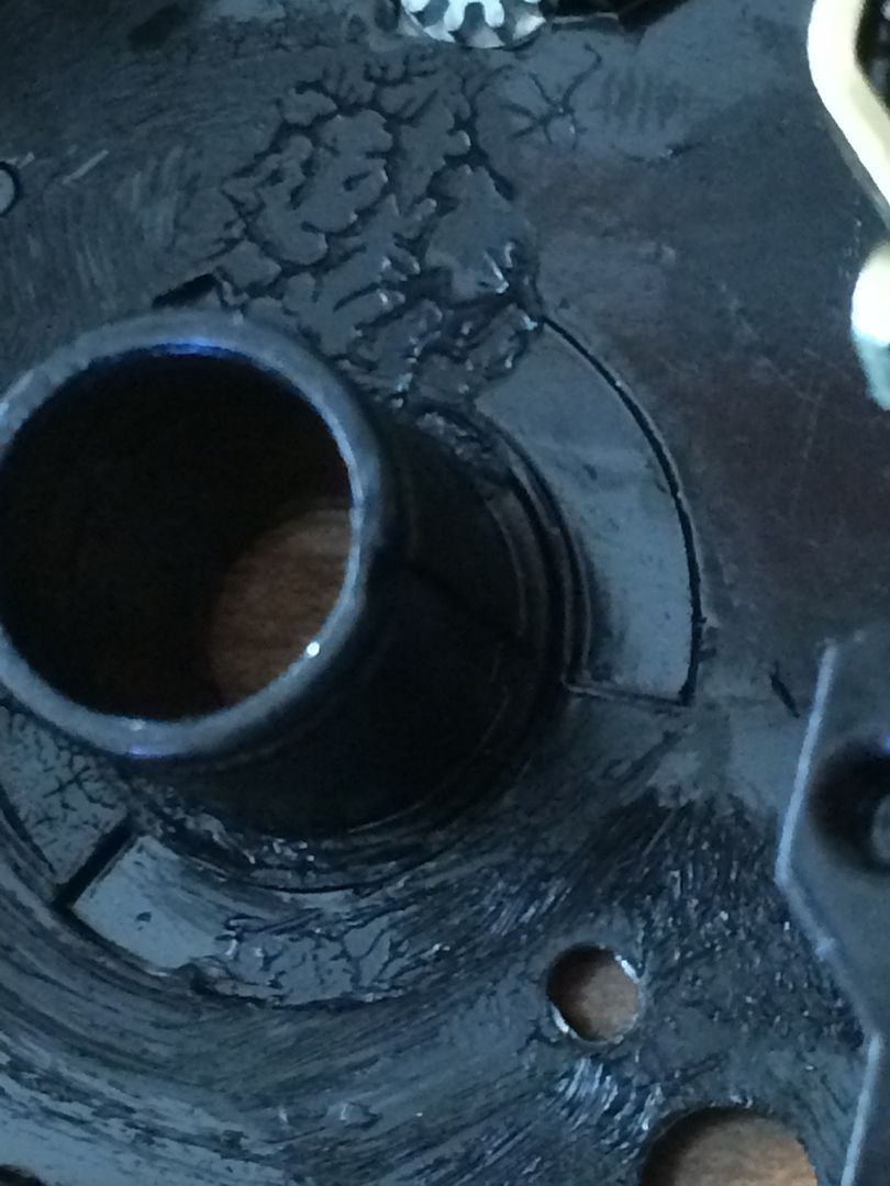
Waaay in the lock, you can see the torque adjuster. Will cover that later.
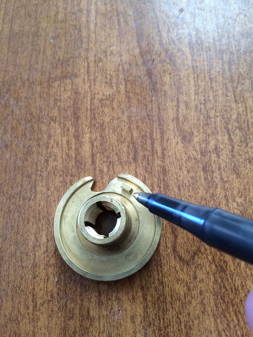
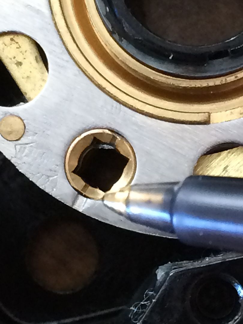
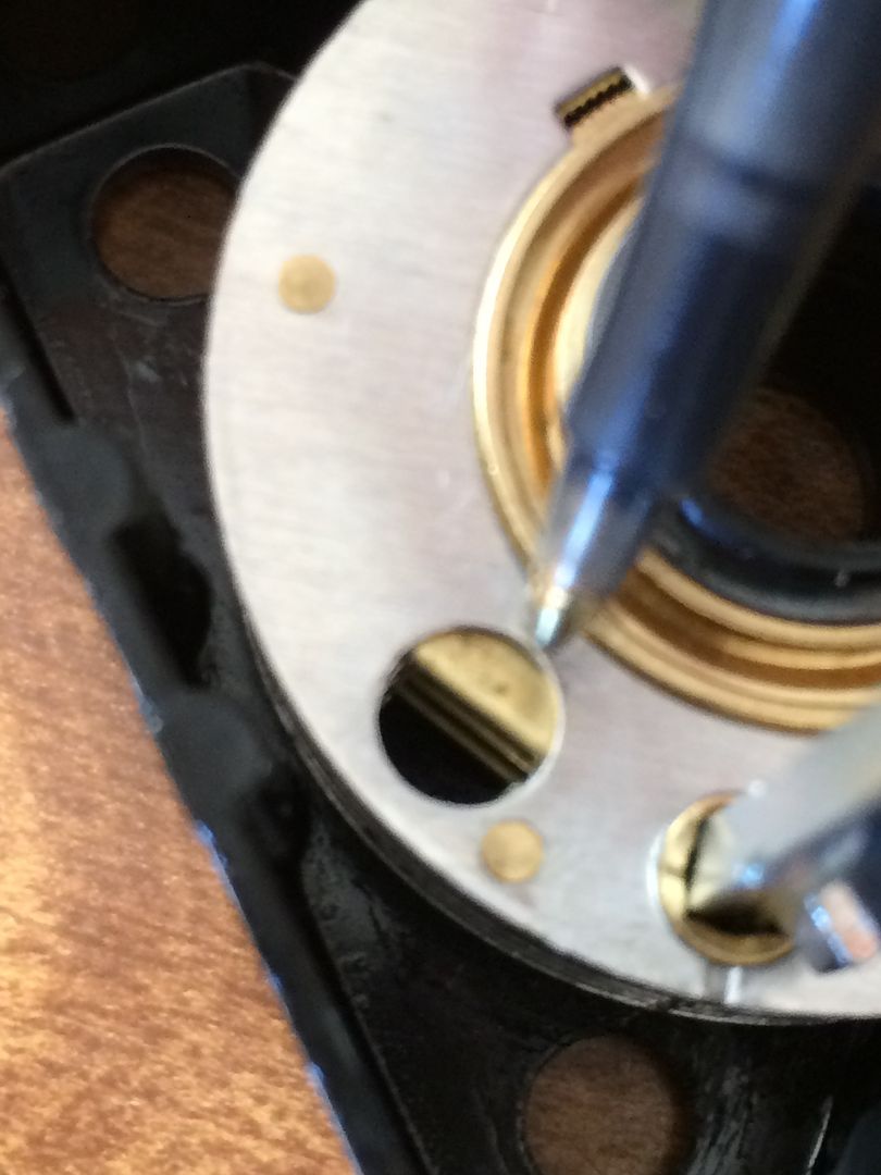
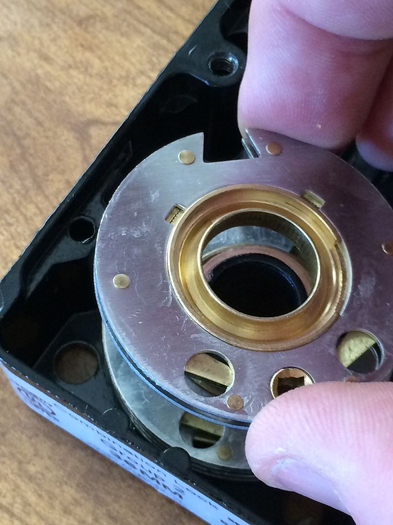
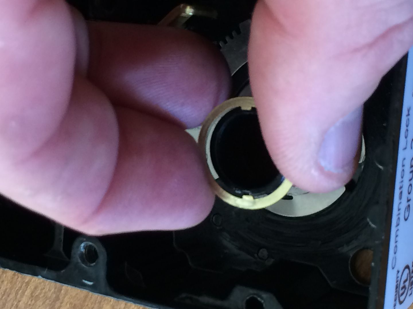
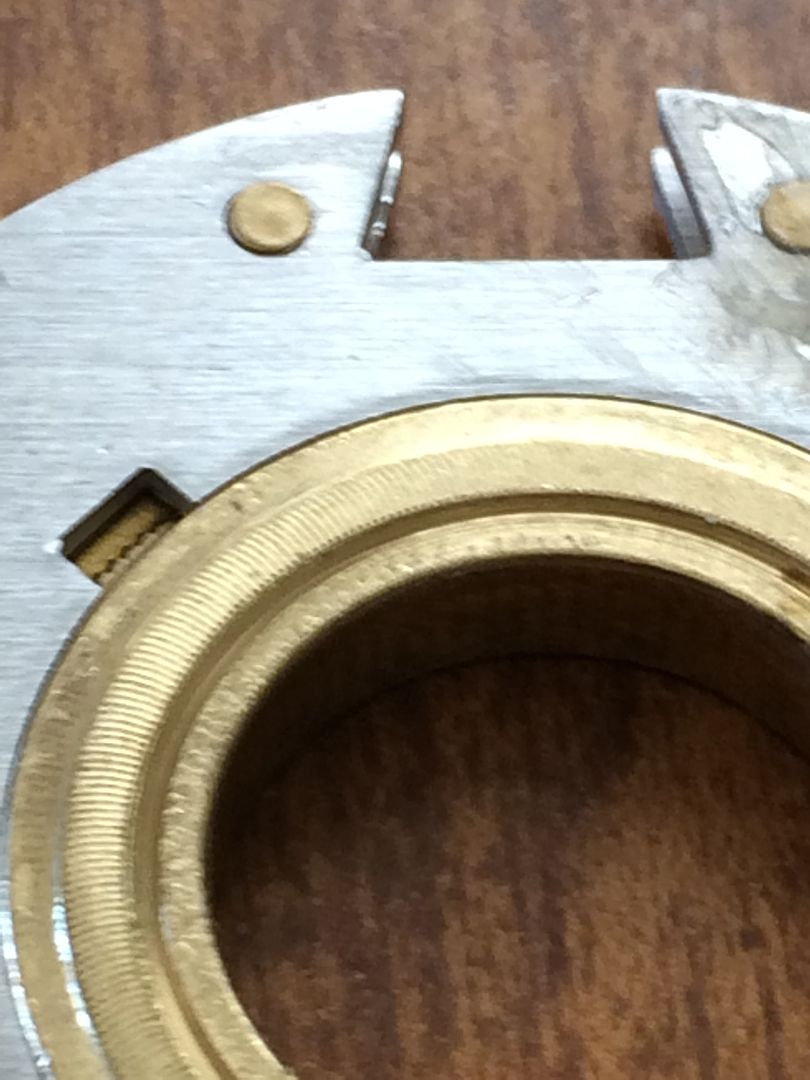
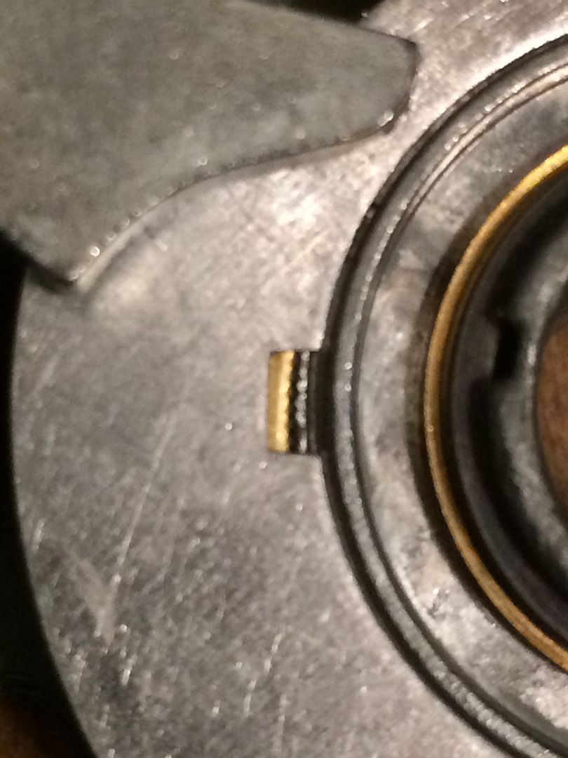
Another visual way of confirming whether the change key hole is turned correctly is to look at the next hole on either side. Here, you can see a thin gap between the brass part inside and the inside edge of the hole. This is locked (ready for use).
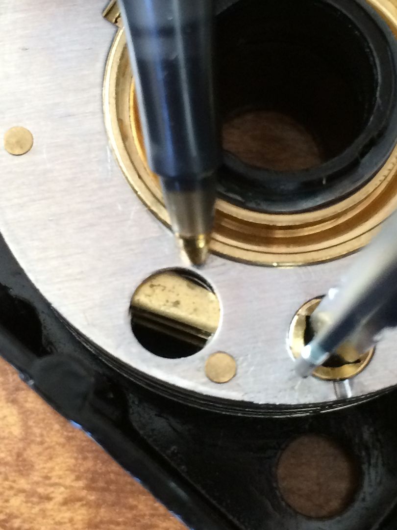
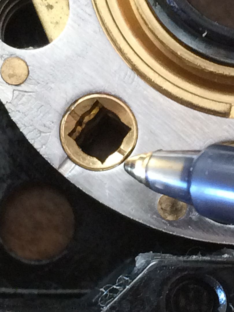
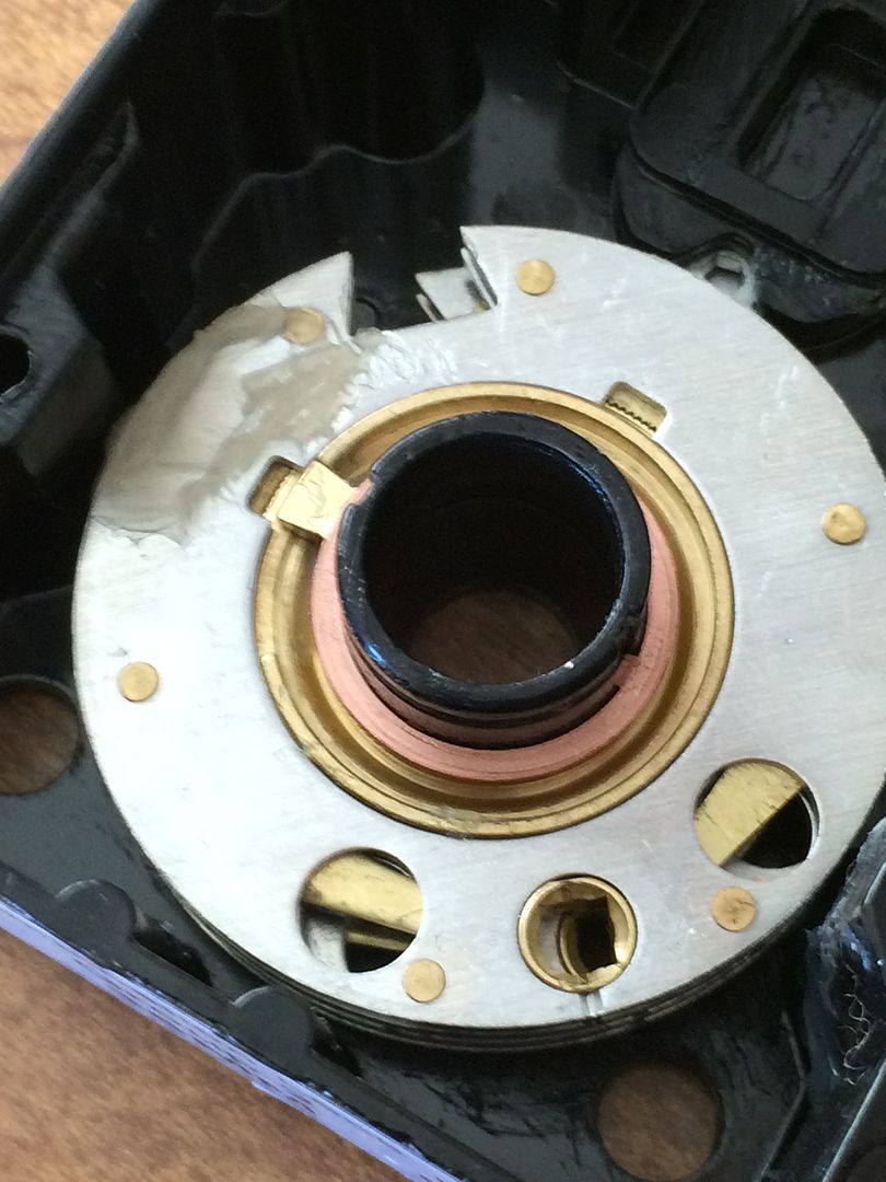
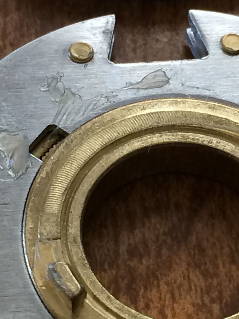
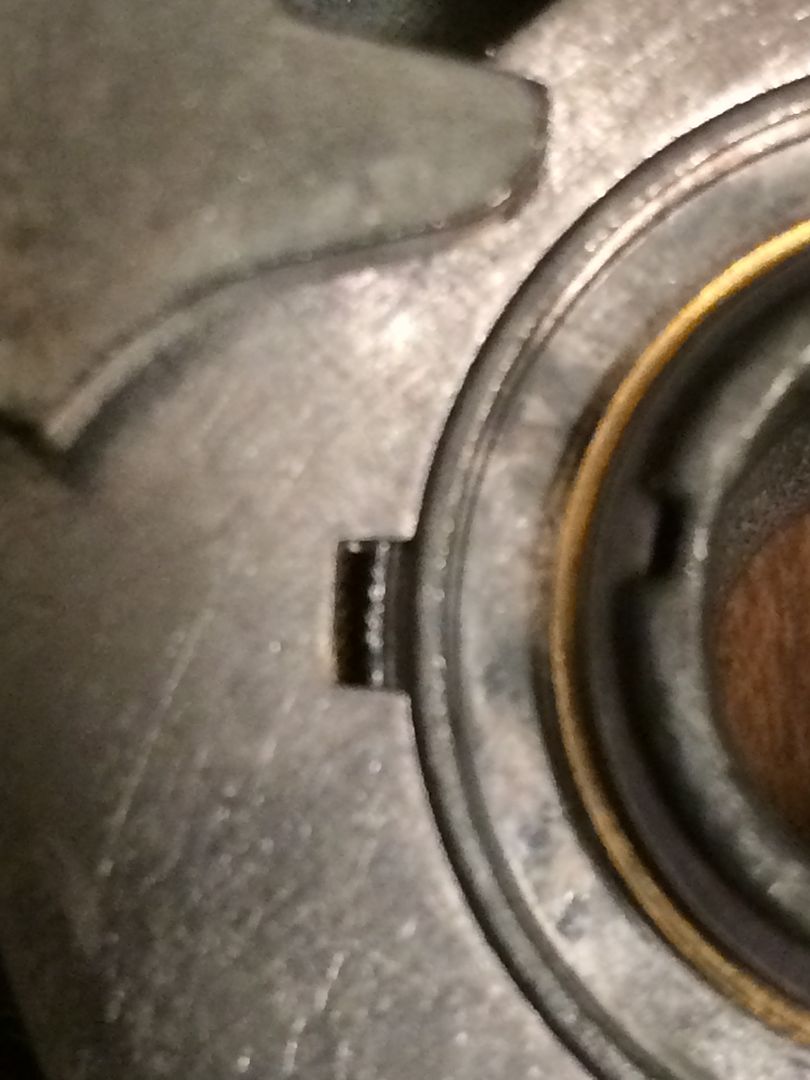
And when there is no gap, the wheel is unlocked (ready for combination to be changed).
OK, now to remove the lever. Take out the bolt.
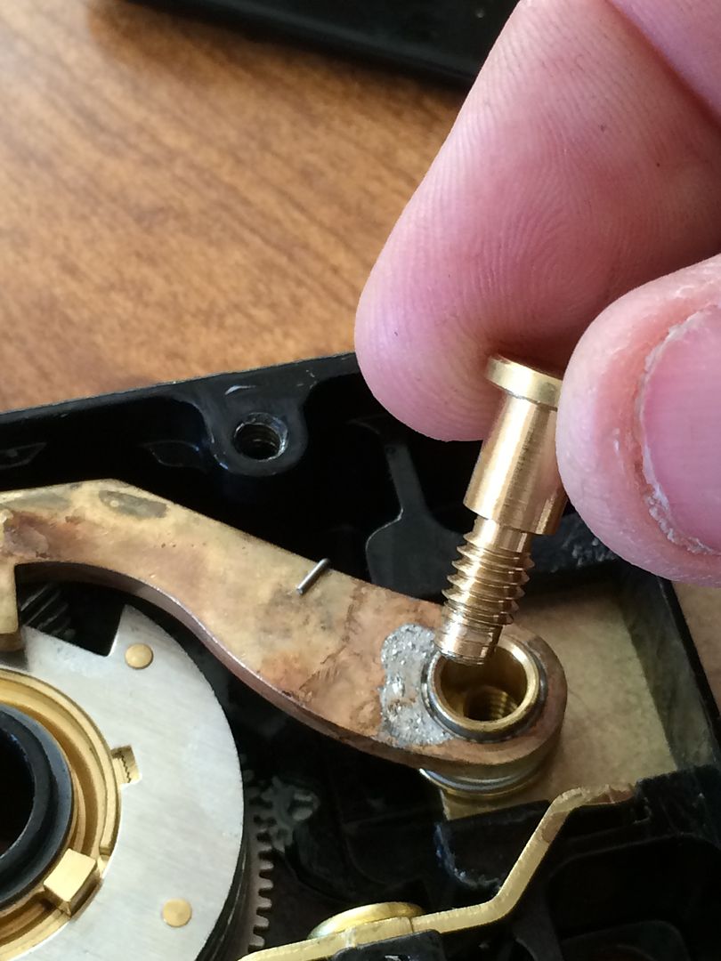
Lift the lever up a little, and you can see that spring better. Do not just keep pulling up the lever, as you do not want to bend the spring.
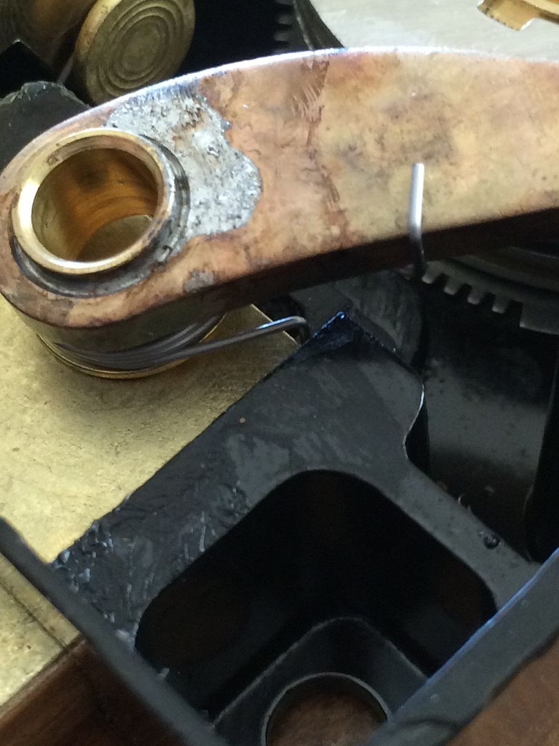
Lift it just enough for the fence to clear the wheels, and allow the lever to rotate until the spring is no longer under tension. Yes, it does turn all this way around to achieve that.
Unhook the lower part of the spring from the bolt and remove the lever.
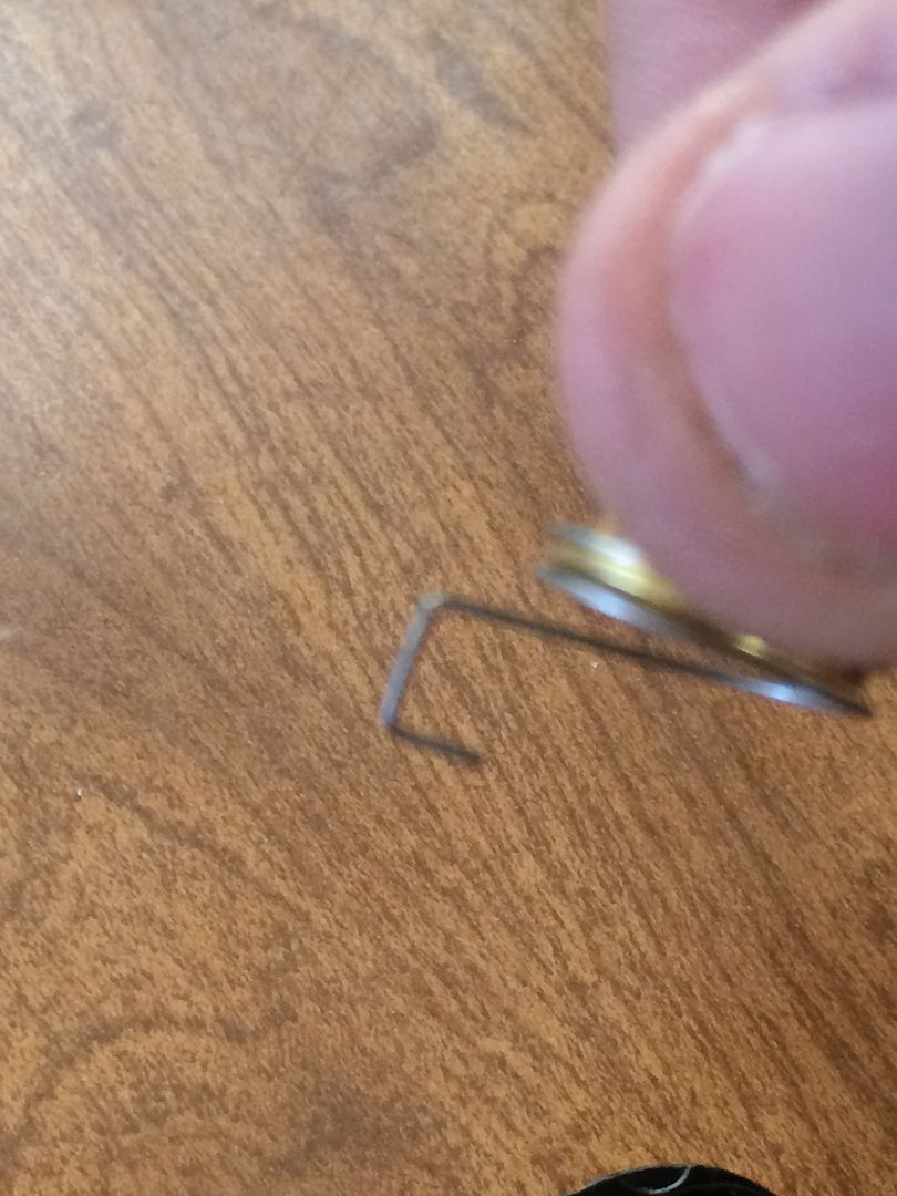
This is the hole in the bolt that spring end fits into.
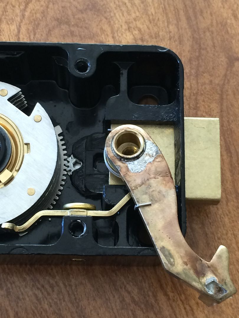
OK, lever is removed. Here’s what is left.
Press down the back cover end of the relocker lever.
With the relocker lever out of the bolt, the bolt can be pulled out. Slowly so you don’t launch the ball bearing.
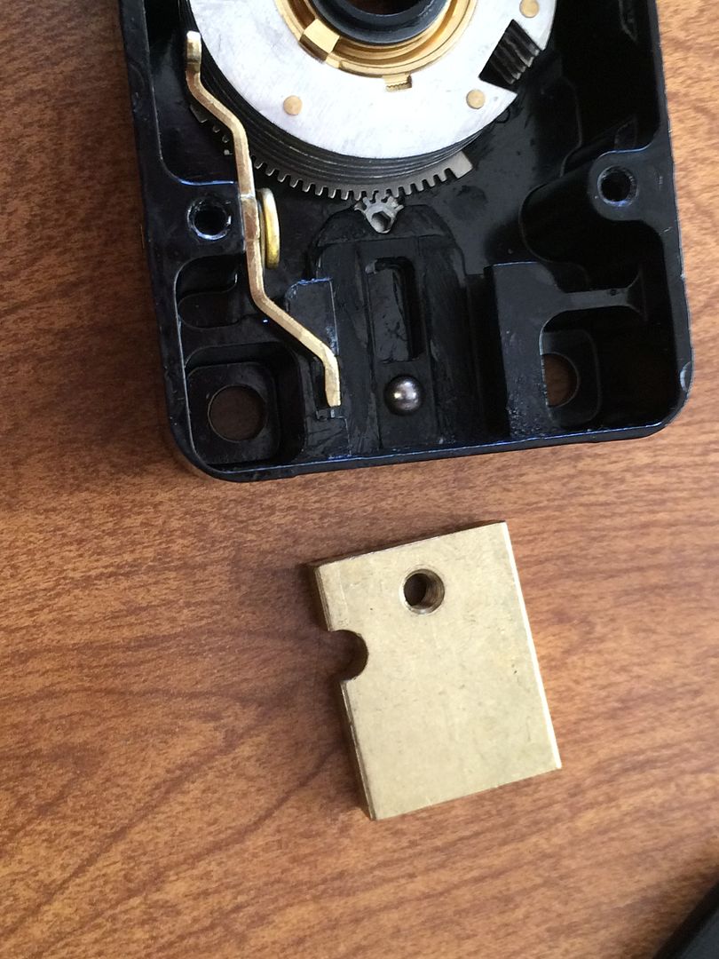
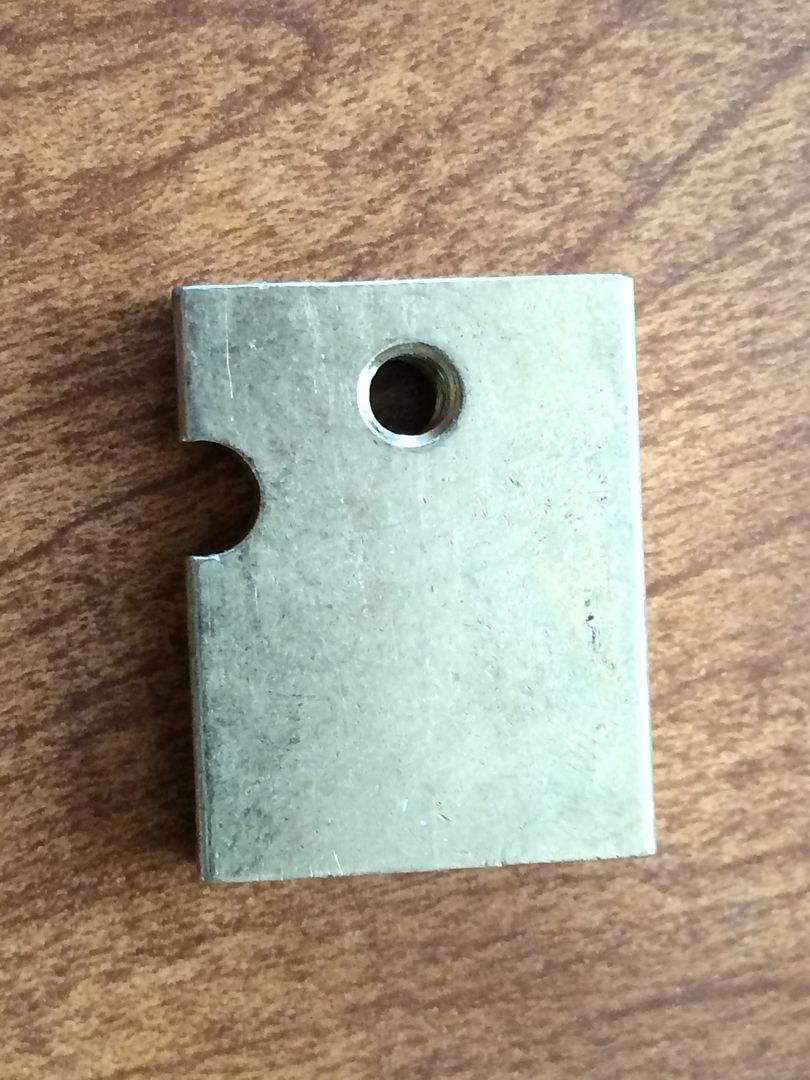
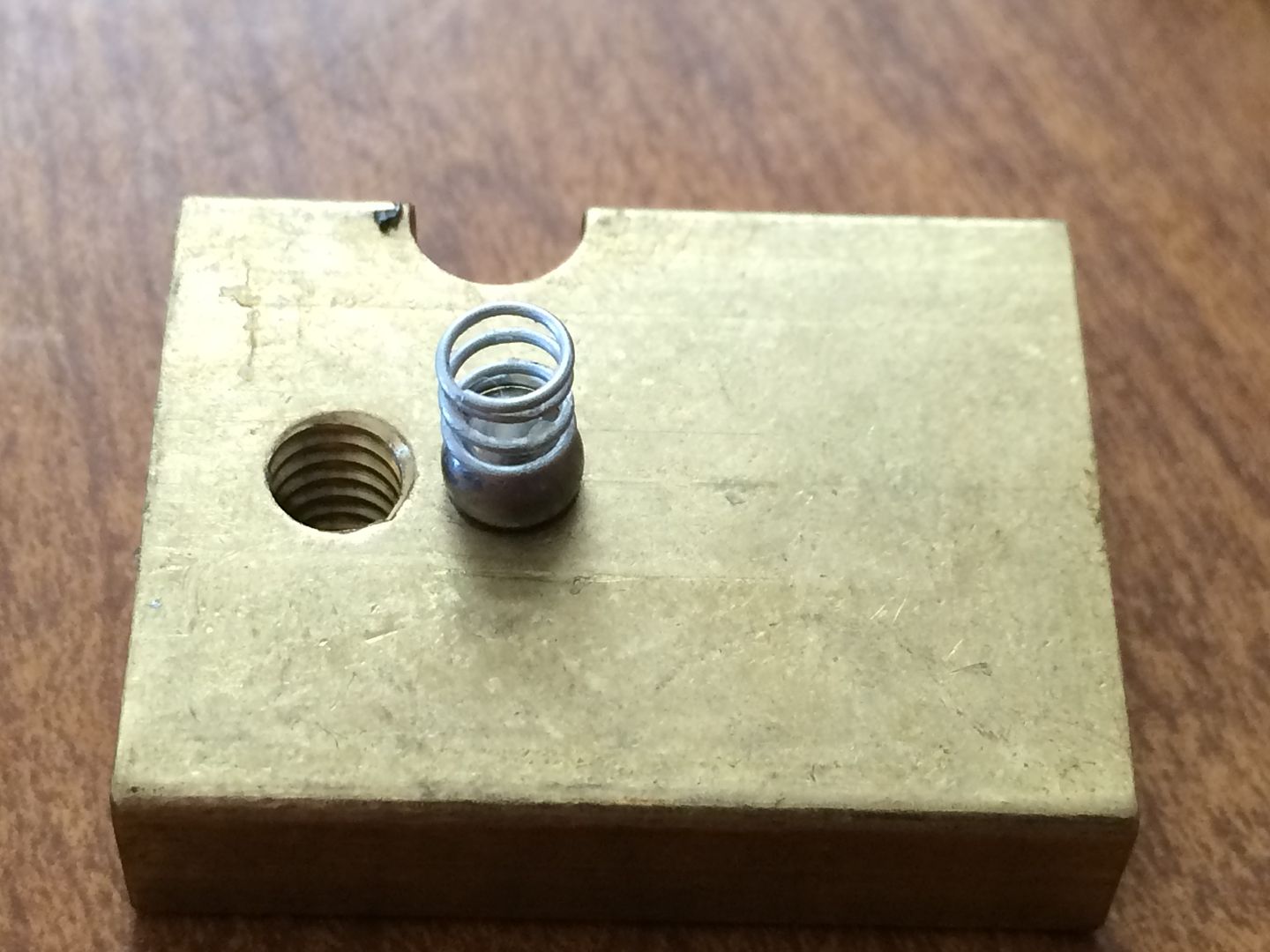
The top side of the bolt. The indent on the left edge is where the relocker holds the bolt. The hole is threaded and is where the screw that holds the lever to the bolt fits.
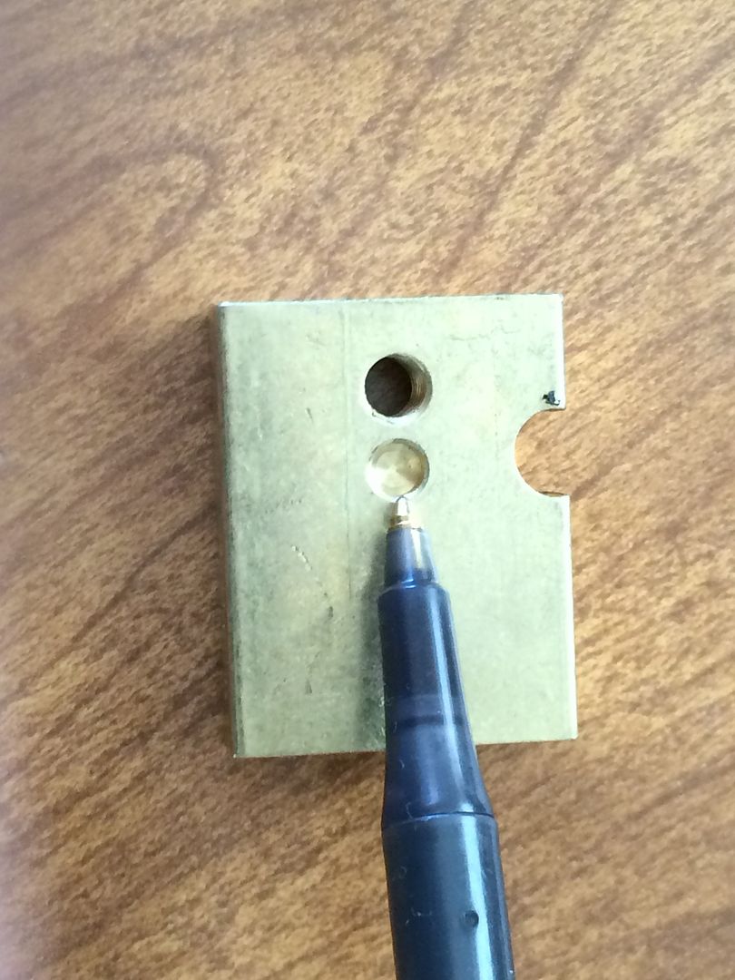
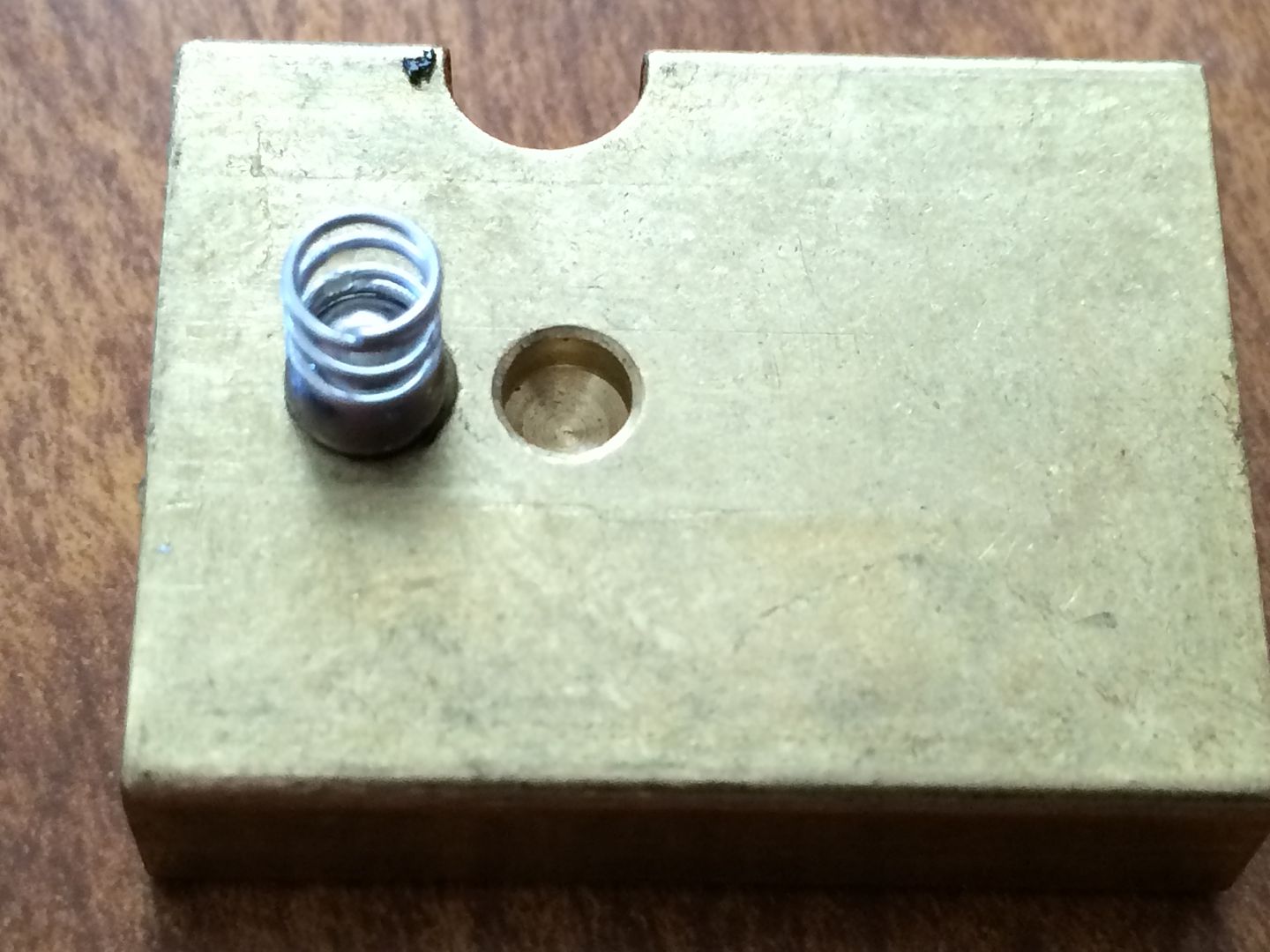
Flip the bolt over, and you see one additional hole. This is an index hole, and the bearing goes partly in here when the bolt is withdrawn, and in the threaded hole with the screw when the bolt is extended.
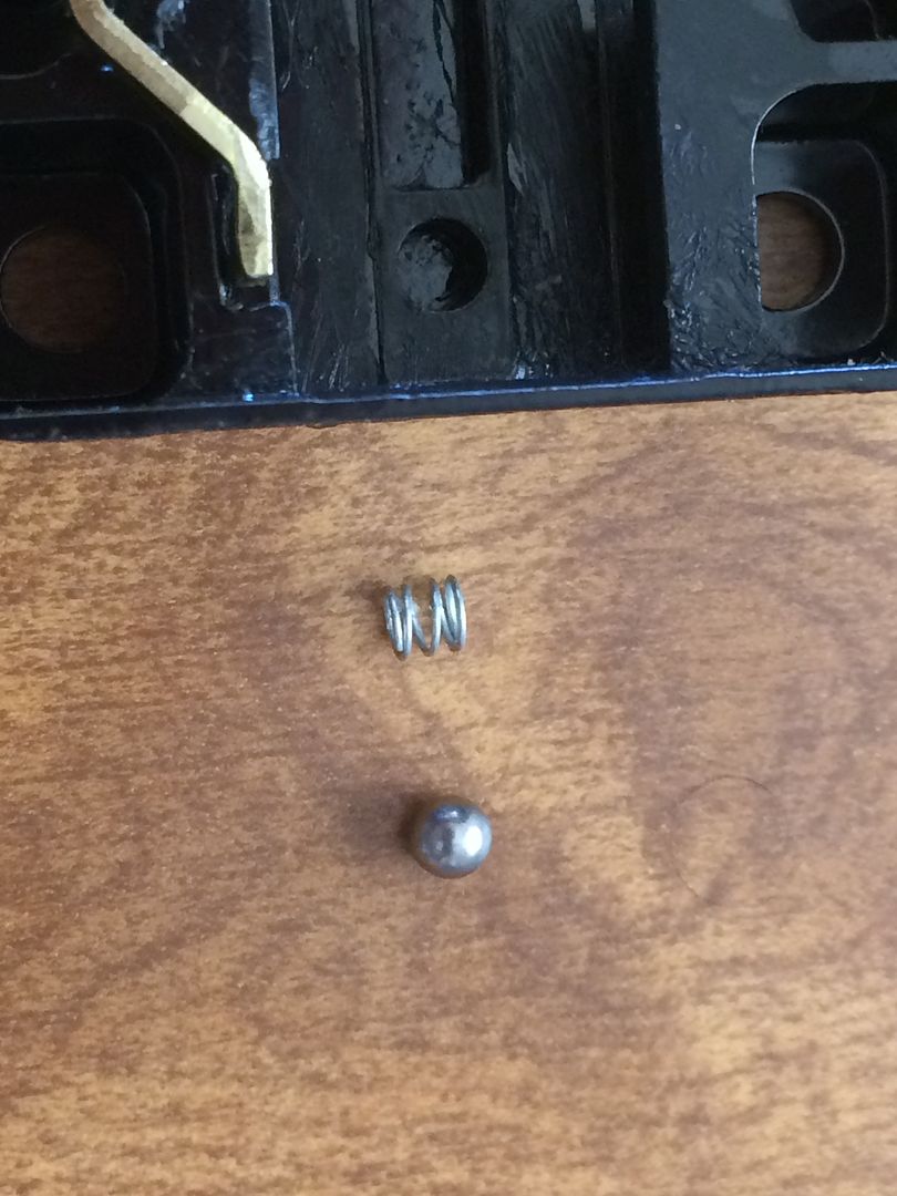
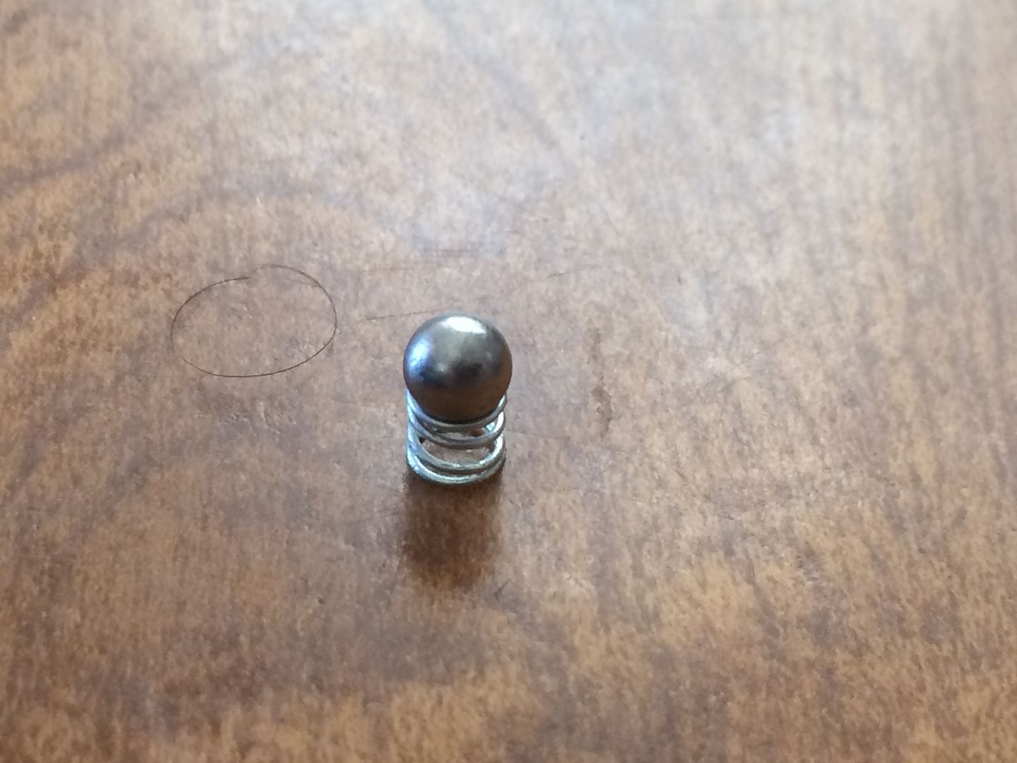
OK, the bearing.
Remove the bearing, and you can see the spring underneath it.
Remove the spring.
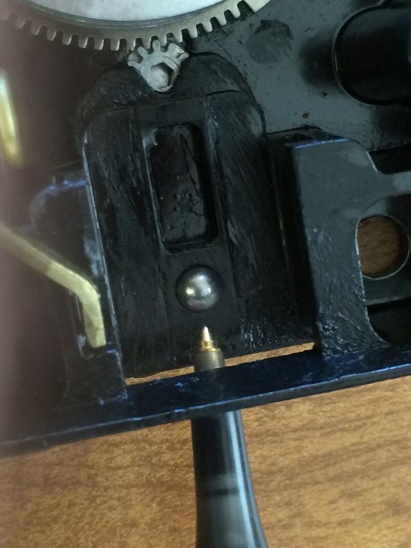
Bolt withdrawn position
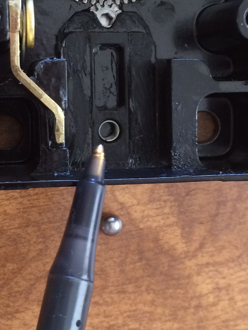
Bolt extended position.
Here you see the relocker lever, spring, and pin that retains it.
This is the pin that retains it.
Why don’t I remove it? Because it is staked in place from the outside of the lock body.
OK, now to remove the wheels, flys, spacers, and so forth.
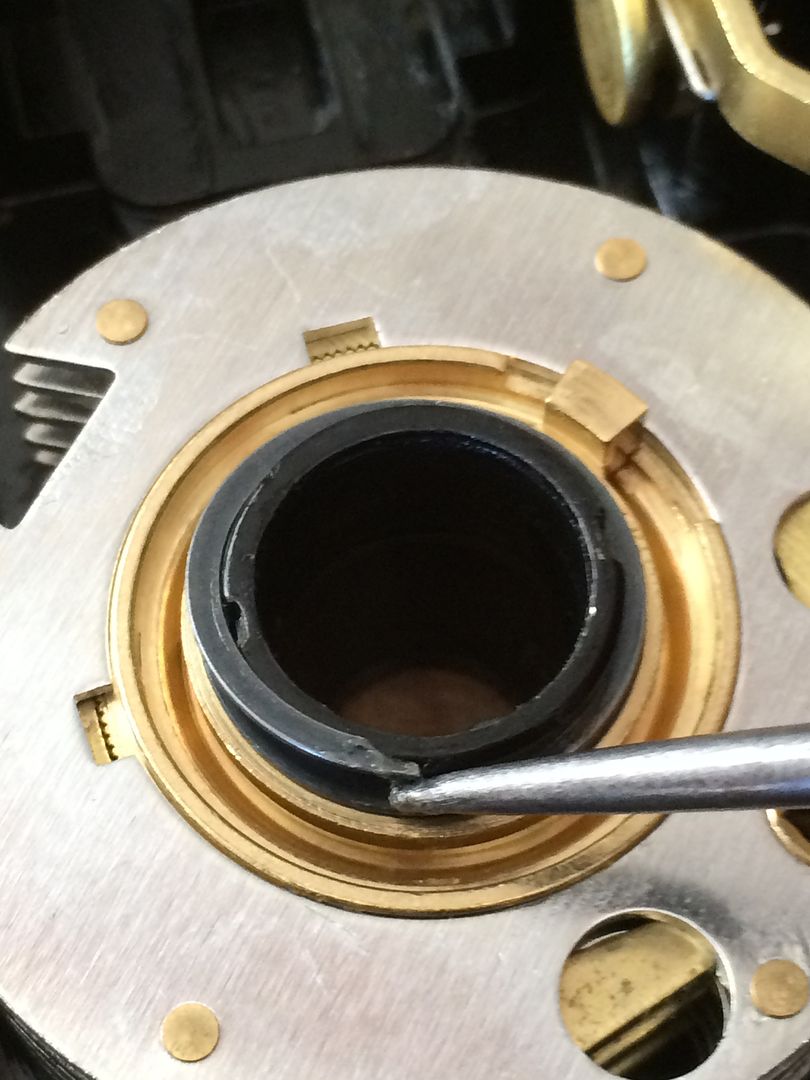
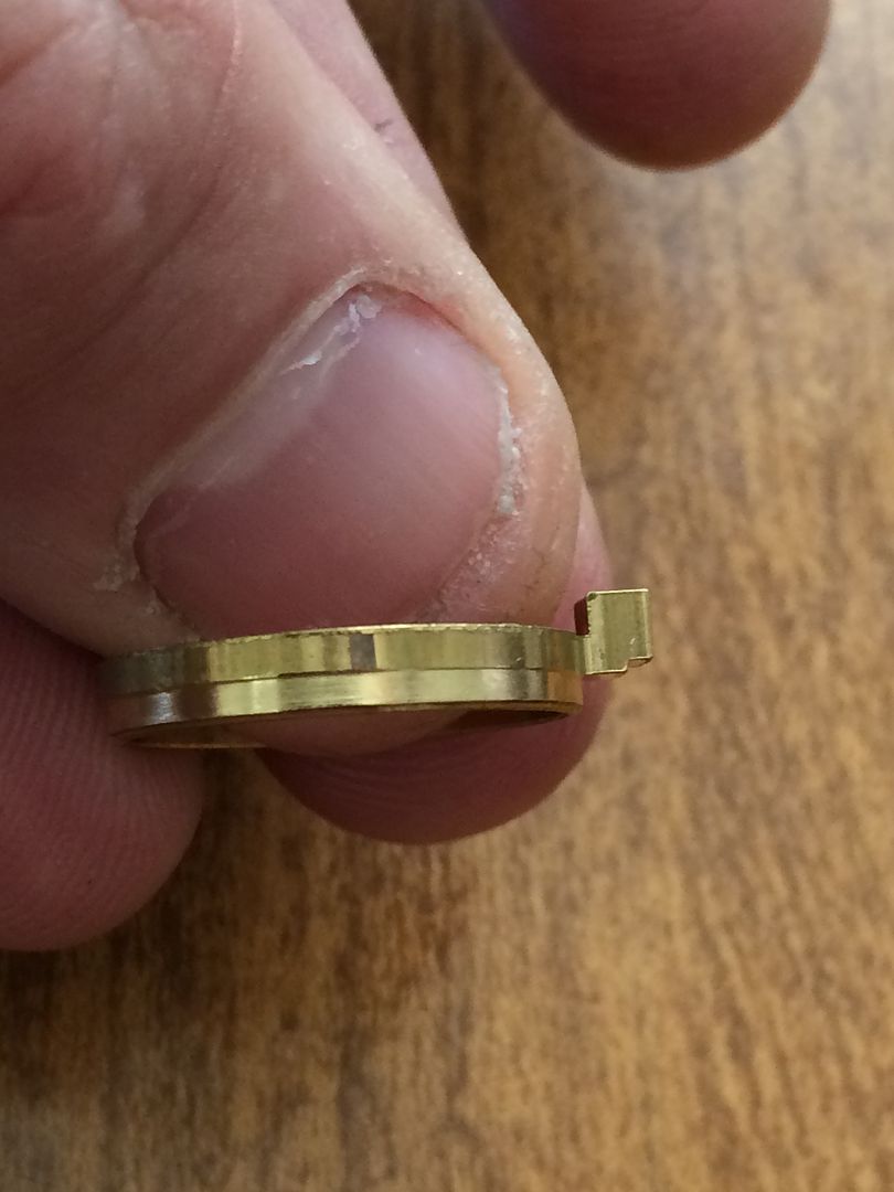
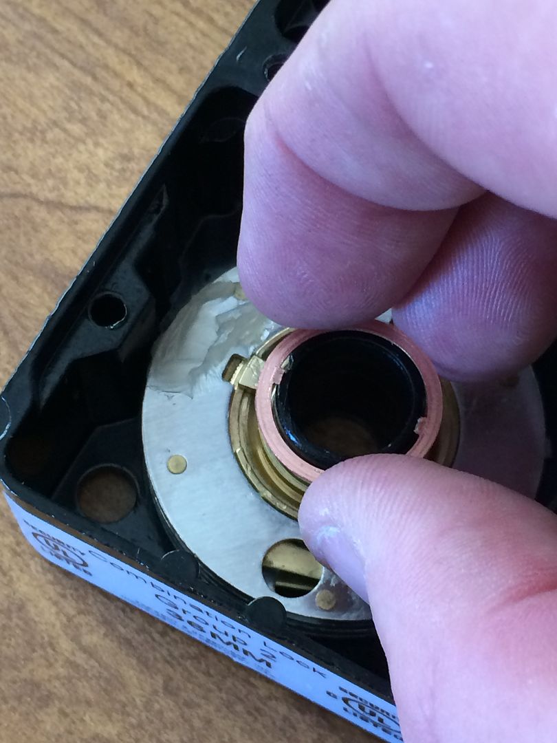
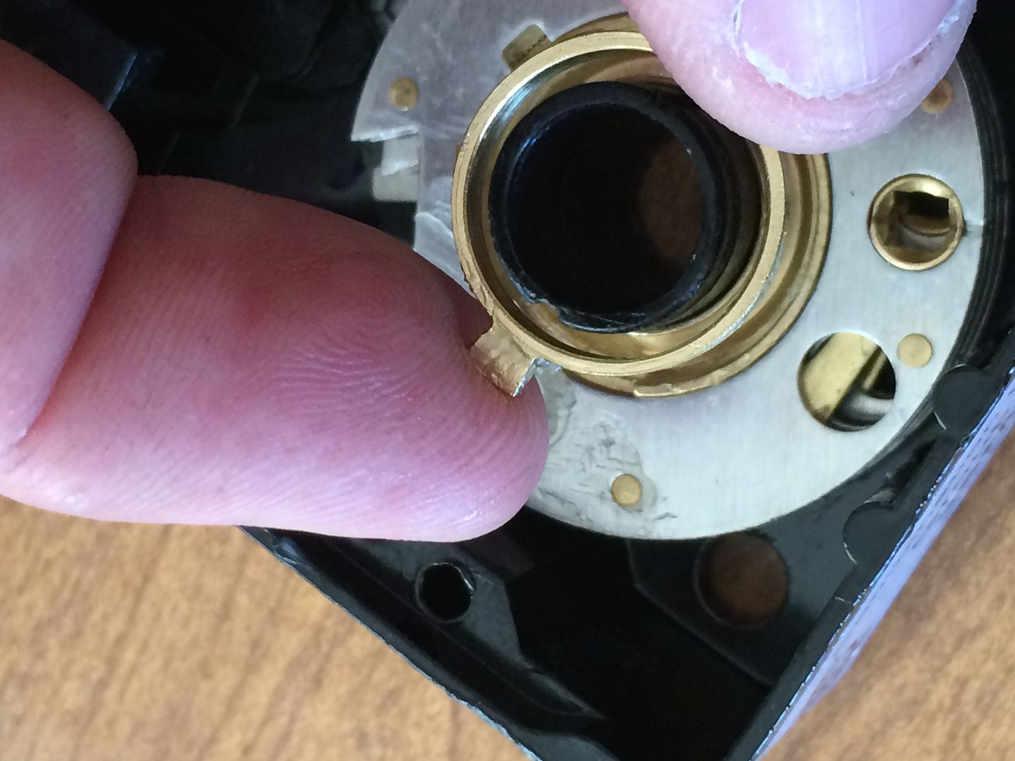
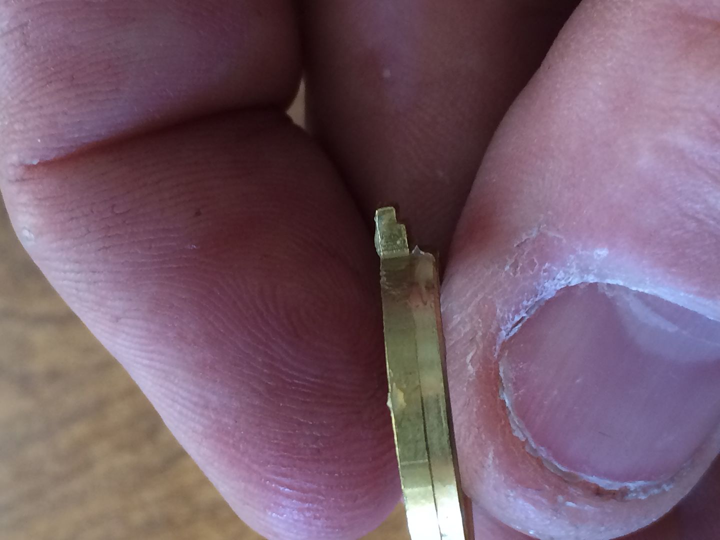
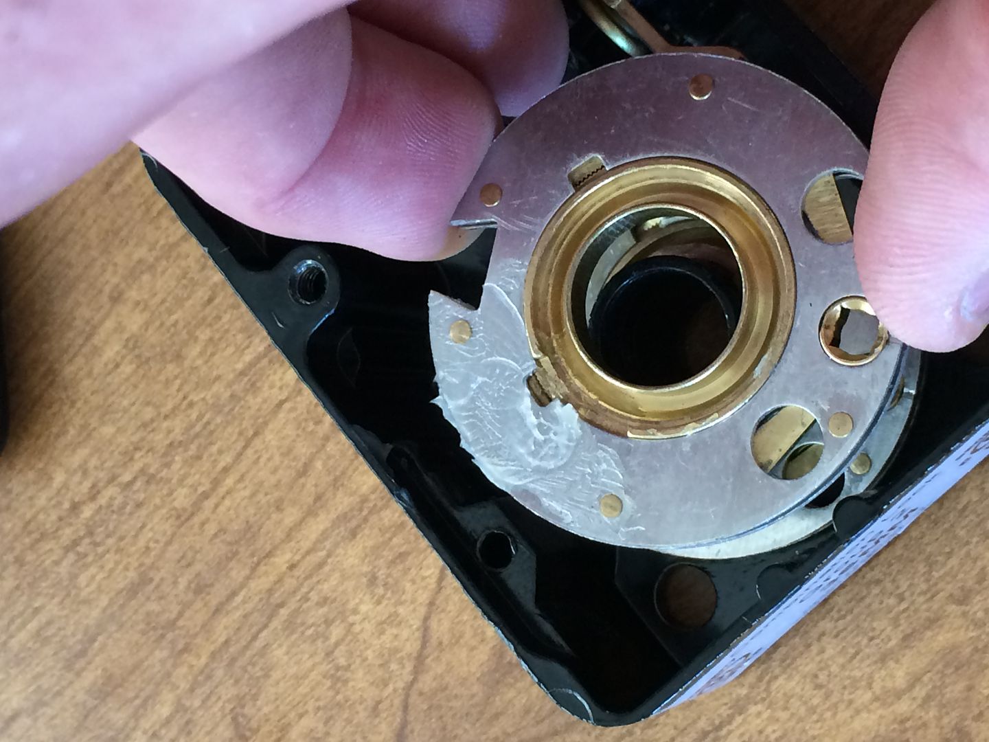
In the center, at the top of the tube is a retaining clip that is flat spring steel that wraps around.
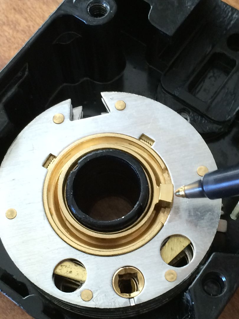
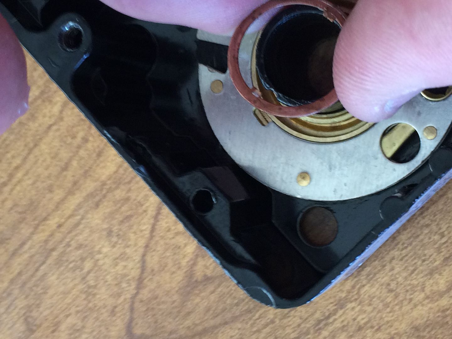
Use a hook or pin to pull the top end outwards and upwards.
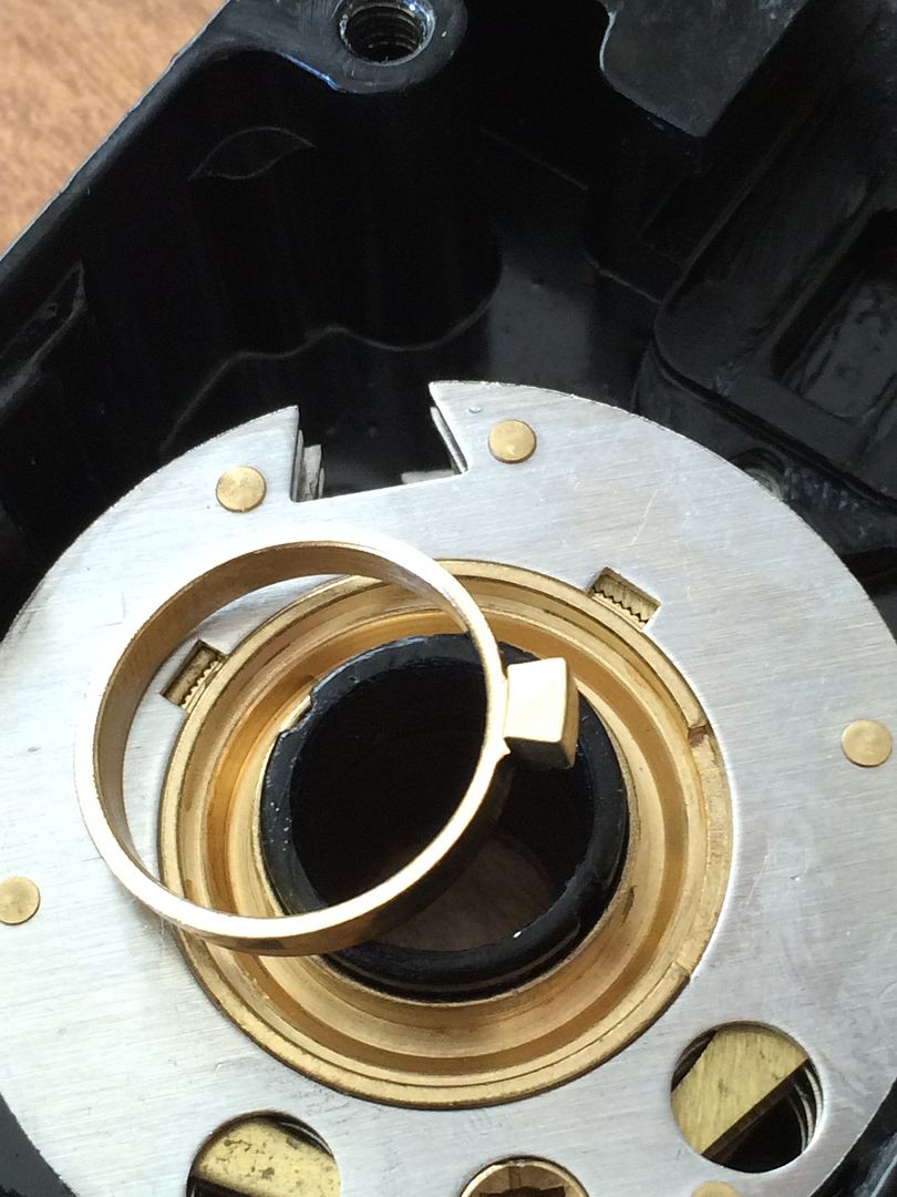
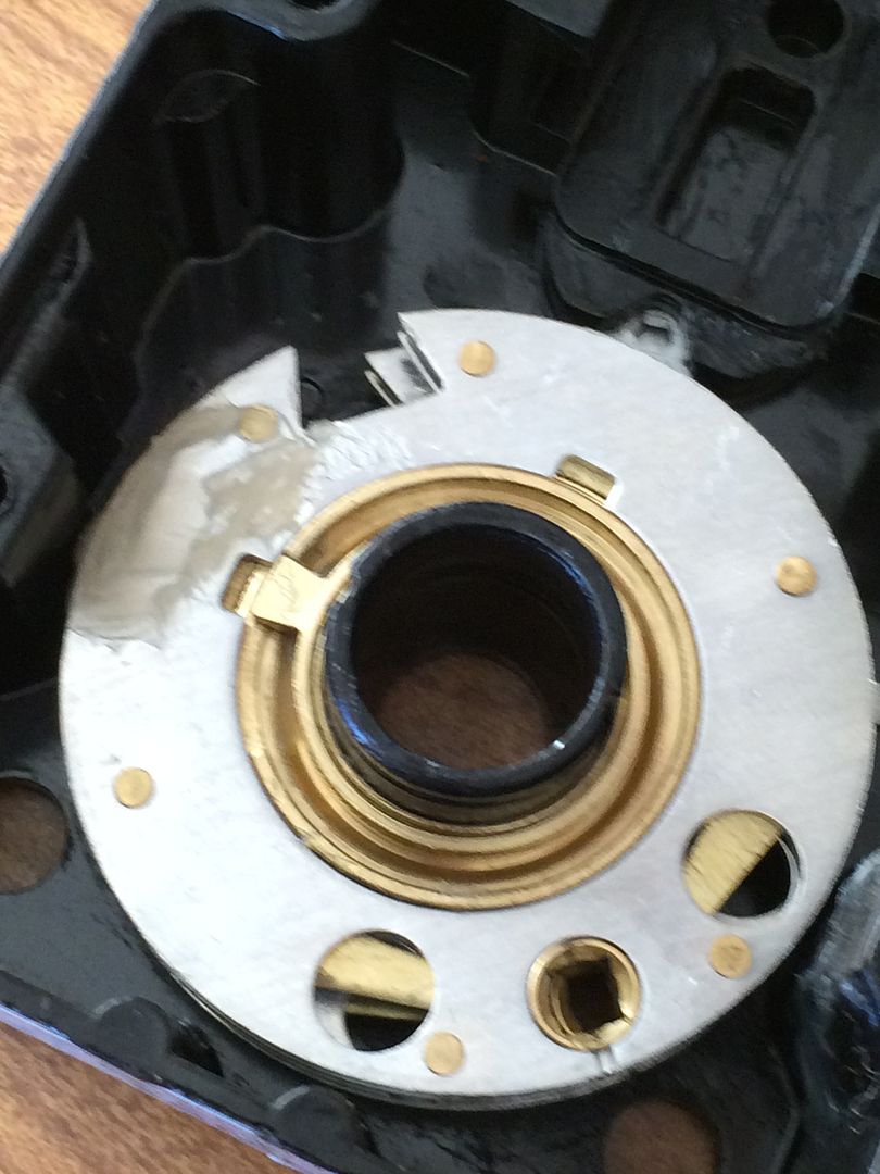
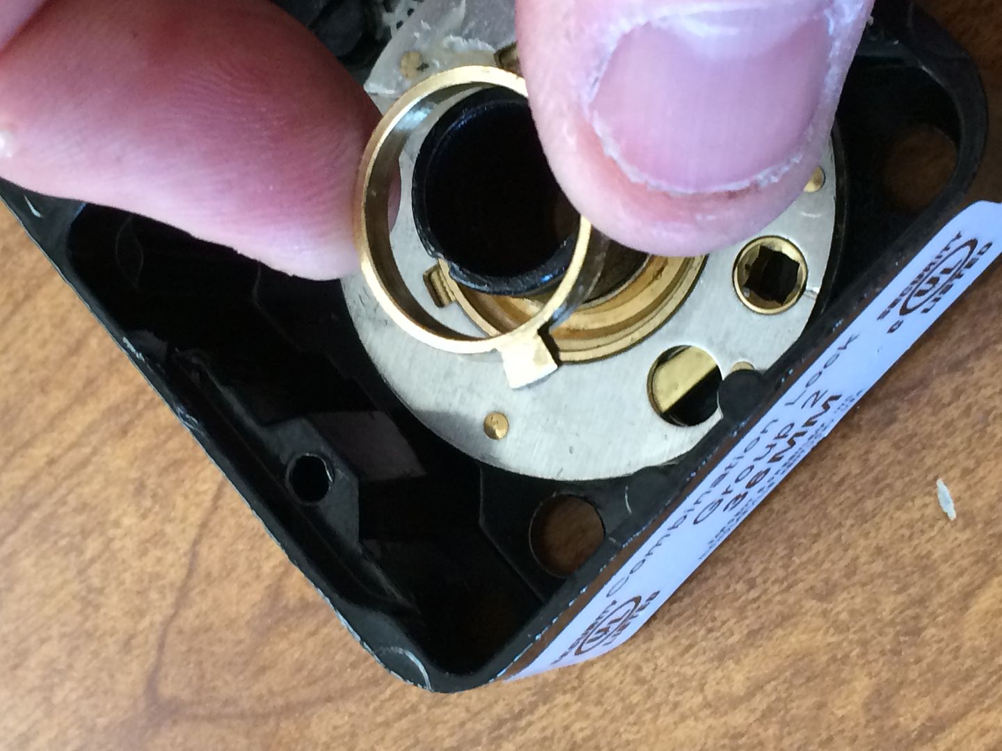
Keep moving the hook around, lifting more of the spring up, until it is entirely off the center tube,
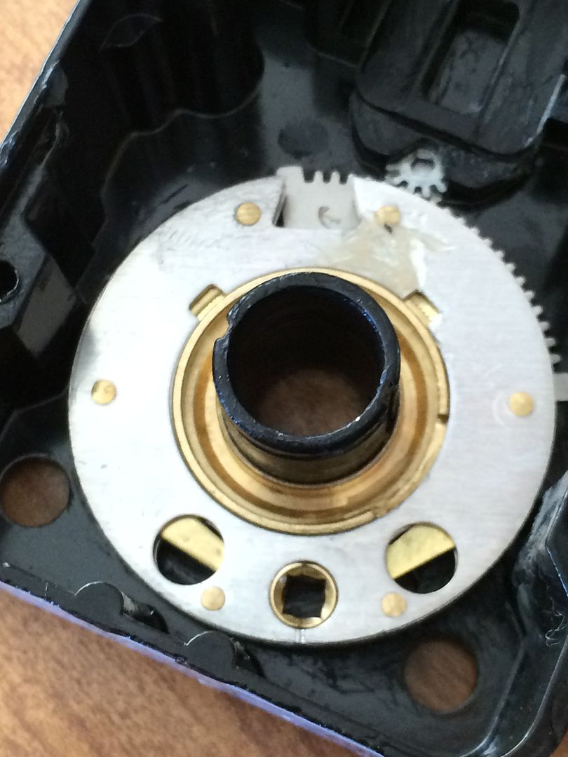
Now this is one of the flys.
It will just lift up.
This one is different than the other two flys, because it is made to be engaged by the drive cam. The part that rises above the top of the fly is a fair bit taller than the other two flys. Here is a side view.
No fly!
Lift off the first wheel.
If you look at the bottom of the wheel you just took off, you will see a post sticking down. This is the part that will engage the fly of the wheel below this one.
Now you can see the copper spacer below the first wheel.
Lift that off, too.
Next remove the fly from the second wheel.
Side view of this fly. The fly from the next wheel is the same as this one. You can see that on the top of the fly, the tab does not rise above the top surface.
Remove the second wheel. (That grease is from the factory. This is a brand new lock that I am taking apart).
And the next copper spacer
Third fly
And third wheel.
Now remove the brass spacer. Different color, and it goes below the third wheel.
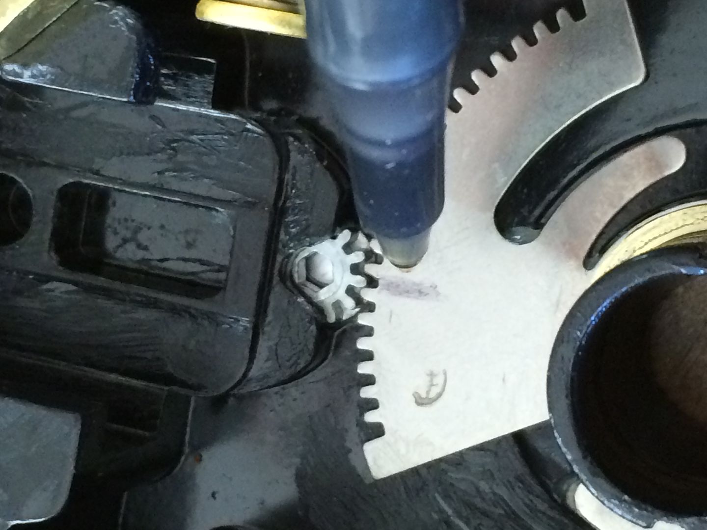
Now you can see the torque adjuster. By using an allen wrench, you can turn that small gear, which will move the big metal part.
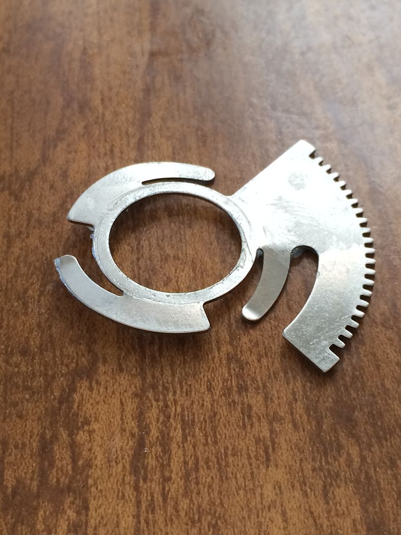
Look closer, and you can see that the big part has three tabs that are angled down.
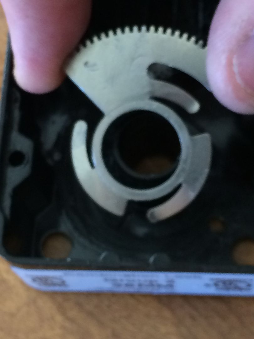
The torque is supposed to be adjusted at the factory, and should require no adjustment according to the manual. So mark the location before removing it.
Here are the ramps that part moves on. If moved one direction, it applies more lifting force to the wheels, requiring more torque to turn the dial. Turn it the other way, and the part goes down the ramps, reducing lifting force and required torque.
This is that gear that is turned with an allen wrench.
Can’t remove it, because it is also staked in place from the outside of the lock body.
Here are the internal parts, laid out in order.
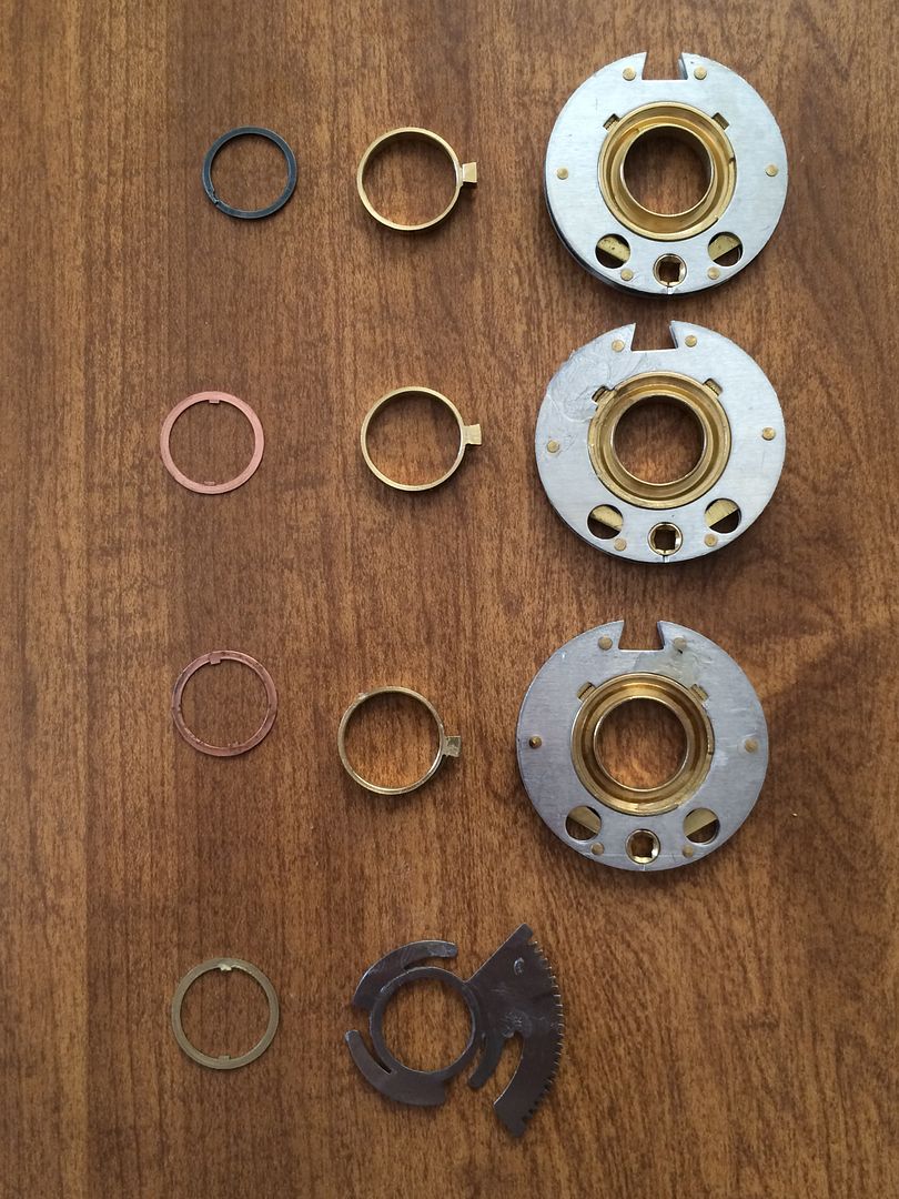
The wheels do have differences. The top two are the same, each with a post on the bottom to engage the fly of the next wheel down.
But the bottom (third) wheel is different. No fly below it, so no post. If it had a post, it would scrape on the parts below.
Another difference can be seen only if you look very closely. The top two wheels have serrations underneath, along the same circle as the post.
The bottom wheel does not.
I don’t know the reason for the serrations on the bottom of the wheel, unless it is meant to help hold the fly better. Hopefully one of our real safe techs can explain them for me/us.
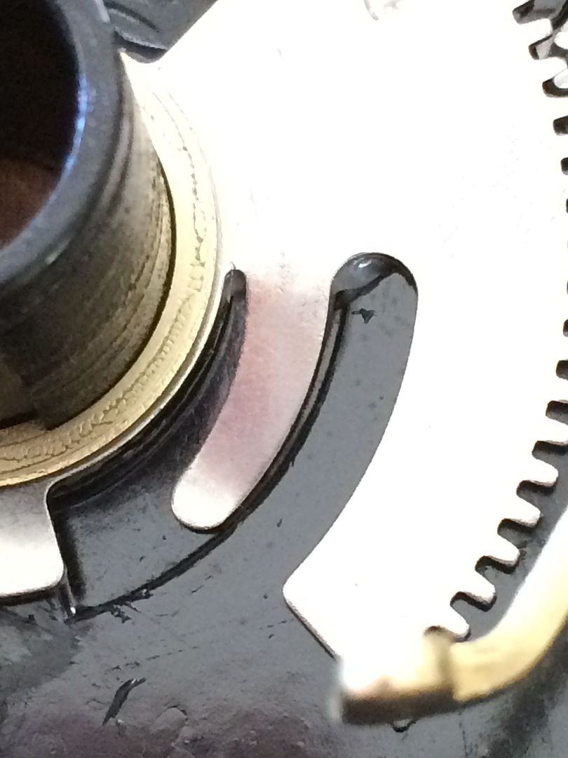
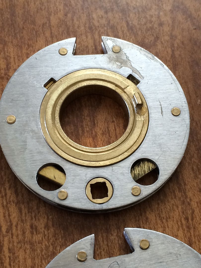
Further, if you look at the picture above, you can see an area that is sort of a cutout, with what looks like two brass parts with serrated teeth.
The original lock from this thread is packaged up and on its way across the pond, so the wheel is slightly different. But you can see what I mean, minus the serrated teeth.
Wheel locked.
Wheel unlocked.
That should explain why the center part of the wheel can stay put when the outer part turns when resetting the combination. And why it will stay at the new location after the change key is removed.
OK, that about does it for what is inside the lock! Hope it answers more questions that it creates.
Gordon